Do you have a question about the WAGO 750-341 and is the answer not in the manual?
Technical description, installation, and configuration guide for the WAGO I/O-SYSTEM 750.
Covers copyright, personnel qualification, conforming use, and technical condition of devices.
Details required qualifications for personnel operating the WAGO I/O-SYSTEM 750.
Outlines relevant standards for installation, safety, and EMC compliance.
Explains the meaning of various symbols used in the manual for warnings and notes.
Provides critical safety notes for device installation, operation, and maintenance.
Highlights key considerations for the initial startup of the 750-341 coupler.
Introduces the WAGO-I/O-SYSTEM 750 as a modular, fieldbus-independent I/O system.
Details mechanical, electrical, and environmental specifications for the system components.
Covers installation position, expansion limits, mounting, and wiring connections.
Details isolation, system supply, field supply, and supplementary power regulations.
Explains grounding procedures for DIN rails and the grounding function.
Discusses the importance and methods of shielding data and signal conductors.
Lists relevant assembly guidelines and standards like DIN 60204 and EN 50178.
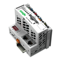
Describes the 750-341 coupler's functionality and role in the I/O system.
Explains the coupler's function in displaying peripheral data via Ethernet.
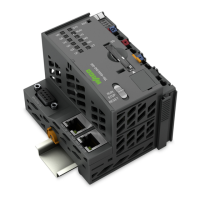
Details the physical view, components, and interfaces of the fieldbus coupler.
Details data exchange methods via MODBUS/TCP and EtherNet/IP protocols.
Provides a step-by-step procedure for starting up a WAGO ETHERNET TCP/IP fieldbus node.
Explains the configuration of the Simple Network Management Protocol (SNMP).
Explains the function and meaning of the LEDs on the coupler for status indication.
Covers fault behavior related to fieldbus failures and internal bus faults.
Provides comprehensive technical specifications for the fieldbus coupler.
Introduces Ethernet as a technology for data transmission in IT and office communication.
Details the principles and regulations for designing a simple Ethernet network.
Explains fieldbus communication protocols like MODBUS TCP and EtherNet/IP.
Describes the Internet Protocol, its segmentation, and IP address classes.
Lists protocols for system administration and diagnosis like BootP, HTTP, DHCP.
Introduces MODBUS as an open fieldbus standard for automation applications.
Details the request/response architecture and exception codes for MODBUS functions.
Displays MODBUS addressing and IEC61131 addressing for process image and internal variables.
Lists internal variables used for diagnostics, configuration, and firmware information.
Introduces EtherNet/IP as an open industry standard extending Ethernet for industrial protocols.
Explains EtherNet/IP's object model, defining objects, classes, instances, and attributes.
Lists CIP Common Classes and WAGO specific classes supported by EtherNet/IP.
Provides an overview of available I/O modules for the WAGO-I/O-SYSTEM 750.
Lists and describes various digital input modules available for the system.
Lists and describes various digital output modules available for the system.
Lists and describes various analog input modules available for the system.
Lists and describes various analog output modules available for the system.
Introduces specialty I/O modules with various functions like counters and serial interfaces.
Lists system modules such as bus extensions, power supplies, filters, and end modules.
Explains the process data structure for I/O modules when using MODBUS/TCP.
Details process data mapping for I/O modules under EtherNet/IP.
Guides on testing fieldbus node functionality using MODBUS master software.
Explains using WAGO Ethernet fieldbus coupler with SCADA software for visualization and control.
Introduces the importance of explosion protection for electrical components in hazardous areas.
Describes primary and secondary explosion protection measures.
Explains classification standards for explosive environments based on CENELEC and IEC.
Outlines classifications according to NEC 500 for North American hazardous areas.
Lists installation regulations for explosive areas in Germany and North America.
Provides definitions for key terms related to networking, protocols, and hardware.
Lists relevant manuals, books, and RFCs for further information.
An alphabetical index of topics covered in the manual for quick reference.
| Product Type | Fieldbus Coupler |
|---|---|
| Bus System | PROFIBUS DP |
| Relative Humidity | 95 % (non-condensing) |
| Protection Class | IP20 |
| Connection Technology | CAGE CLAMP® |
| Number of I/O Modules Connectable | 64 |
| Protocol | PROFIBUS DP |
| Supply Voltage | 24 V DC |
| Operating Temperature | 0 … +55 °C |
| Storage Temperature | -40°C to +85°C |
| Transmission Speed | 9.6 kbit/s to 12 Mbit/s |