Do you have a question about the WAGO 750-8215 and is the answer not in the manual?
Specifies applicability to PFC200; G2; 4ETH CAN USB controller and FW version 03.02.02(14).
Manual is copyright-protected. Unauthorized use by third parties is prohibited.
Lists third-party trademarks used in the documentation, omitting ® and TM symbols.
Explains symbols for Danger, Warning, Caution, Notice, and Important Note.
Details Decimal, Hexadecimal, and Binary number notation formats.
Explains font conventions for paths, menus, input, values, buttons, and keys.
Covers subject to changes, personnel qualifications, compliant use of 750 Series, and device conditions.
Essential safety precautions for device installation and operation, including enclosure and connection.
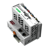
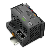
Overview of the controller's physical components and their labels.
Details front and side labeling, including device designation and serial number.
Describes data contacts, local bus, power jumper contacts, CAGE CLAMP, service, network, and CANopen connectors.
Explains power supply, fieldbus/system, memory card, and network indicating elements.
Details the mode selector switch and reset button functions.
Describes the location and function of the SD memory card slot.
Provides a schematic diagram of the controller's internal connections and interfaces.
Covers mechanical, system, power supply, clock, programming, bus, and Ethernet specifications.
Details interface configuration, network security, host/domain name, routing, and network services.
Explains memory card operations like formatting, data backup, restore, and file management.
Information on e!RUNTIME runtime system licensing and e!COCKPIT software requirements.
Specifies allowed installation positions and notes on vertical mounting end stops.
Defines maximum total length of fieldbus nodes and I/O module limits.
Details carrier rail properties and guidelines for optimal system setup and electrical contact.
Explains spacing requirements between components for heat transfer, installation, and wiring.
Describes the procedure for snapping fieldbus couplers, controllers, and I/O modules onto a carrier rail.
Provides instructions for connecting conductors to WAGO CAGE CLAMP connections.
Explains the power supply concept, including overcurrent protection and fuse recommendations.
Ensures proper installation and connection before switching on the controller.
Guides on finding the host PC's IP address using the MS DOS prompt.
Details methods for setting IP addresses via DHCP, CBM, and WAGO Ethernet Settings.
Describes how to perform a ping network function to check controller reachability.
Instructions for changing standard passwords for WBM and Linux users.
Provides guidance on safely shutting down and restarting the controller using software reboot.
Explains how to perform warm start, cold start, and software resets using mode selector and reset button.
Covers configuration methods: WBM, CBM, CODESYS, and WAGO Ethernet Settings.
Provides information on e!COCKPIT installation and CODESYS 3 documentation.
Lists priorities implemented for controller tasks for CODESYS 3 documentation.
Details memory sizes for program, data, flags, retain, and function block limitation.
Provides an overview of PFC-OUT, PFC-IN, and Modbus Special registers.
Details watchdog configuration, status registers, electronic nameplate, and process image versions.
Explains how to estimate Modbus master CPU load based on cycle time and data points.
Describes communication objects and user objects compiled in the object directory.
Details device type, error register, pre-defined error field, and synchronization objects.
Explains process data exchange via communication objects and fieldbus-specific addressing.
Shows allocation of PFC variables to object directory entries for CODESYS access.
Guides on selecting the master and setting master parameters, baud rate, and node IDs.
Explains adding CANopen slaves and configuring their variables and parameters.
Describes creating diagnostics using CODESYS and integrating BusDiag.lib.
Details controller connection to PROFINET via X11 and X12 interfaces and MRP client support.
Explains PROFINET parameter setting using e!COCKPIT and Data Point Configurator.
Describes operating and status messages indicated by LEDs: Power Supply, Fieldbus/System, Network.
Explains flashing sequences for displaying fault/error codes and arguments.
Provides step-by-step instructions for inserting and removing the memory card.
Details procedures for performing firmware upgrades and downgrades.
Instructions for downloading, renaming, transferring, and restarting the controller for root certificates.
Provides safety warnings and instructions for removing the controller from the assembly.
Guidelines for proper disposal of electrical and electronic equipment according to WEEE.
Information on packaging materials and environmentally friendly disposal practices.
Provides marking examples for Europe (ATEX/IECEx) and USA/Canada (NEC/CEC).
Covers special notes on explosion protection and specific installation requirements for hazardous areas.
Describes process image representation for I/O modules and process value configuration.
| Brand | WAGO |
|---|---|
| Model | 750-8215 |
| Category | Controller |
| Language | English |