22
Pro Dry Instruction Manual | Walker Filtration | www.walkerltration.com
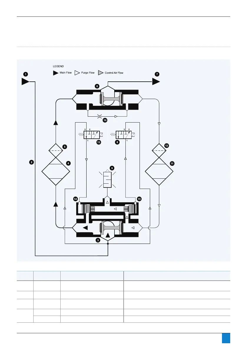
Section 5: Operation
1. Air inlet
2. Down pipe
3. Inlet shuttle valve
4. LH desiccant bed
5. LH dust filter
6. Outlet shuttle valve
7. Air outlet
8. RH exhaust valve 3/2 NO
solenoid valve
9. Exhaust silencer
10. Purge valve
11. RH desiccant bed
12. RH dust filter
13. LH exhaust valve 3/2 NO
solenoid valve
Figure 5.4: Process & Instrumentation diagram (PD045 – PD365)
Note: Diagram shown in one of
six possible positions, Left Tower
Drying, Right Tower Purge.
Certain feature are intentionally
shown out of position for reasons
of clarity.
Stage
Time (Seconds) SV Valve Status Dryer Operation
1. 0 Left valve closed, right valve opens Left tower at pressure (drying), right tower depressurizes and
Then purges (this stage is shown on pd2 pneumatic schematic)
2. 120 Both valves closed Right tower repressurizing
3. 140 Left valve opens, right valve closed Left tower depressurizes and then purges, right tower at
Pressure (drying)
4. 260 Both valves closed Left tower repressurizing
280 Back to stage 1 -
 Loading...