39
Pro Dry Instruction Manual | Walker Filtration | www.walkerltration.com
Using an Electronic Pressure Switch for Purge Control
The best choice if using a pressure switch is to select an
electronic programmable type pressure switch which is
effectively a pressure transmitter and process controller
built into one device. While signicantly more costly than
a standard pressure switch, an electronic programmable
pressure switch can be setup to provide a much more
customized operation. Typically, the dead band can be reduced
or eliminated so that an immediate reaction to changes, in
system pressure indicating air ow, can be obtained.
It is extremely important to understand that the purge may
only be shut off during periods of low or no demand. This
feature, if used otherwise, can result in permanent damage
to the desiccant beds resulting in loss of drying capacity
and possibly mechanical failure. The cartridges must not be
allowed to become fully saturated at any time.
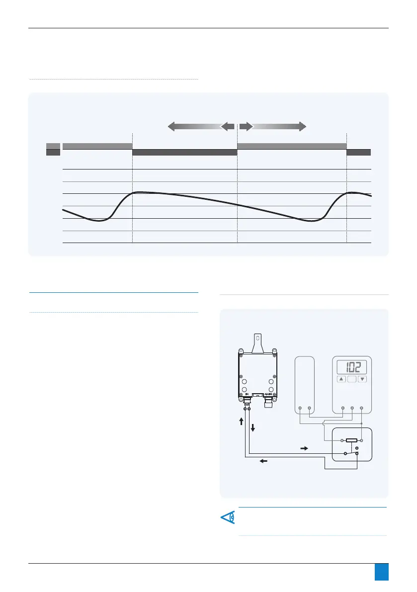
The following schematic offers an overview of the devices
mentioned as they might be connected for use in controlling
a dryer’s purge function. Please note that specic details
differ between device manufacturers, so in all cases the
manufacturer’s specications should be adhered to.
Section 7: Energy Management
Figure 7.4 Using an Electronic Pressure Switch for Purge Control
DRYER
CONTROLLER
DC POWER
SUPPLY
ELECTRONIC
PRESSURE SWITCH
RELAY
* Normally Closed, open to turn purge off
PIN 1 (puts out
+5 VDC signal)
PIN 2
SIGNAL BACK
SIGNAL OUT
N.C.*
N.O.
N.C.*
N.C.*
N.O.
* Normally Closed, open to turn purge off
MANUAL SWITCH
(Field Installed)
DRYER
CONTROLLER
PIN 1 (puts out +5 VDC signal)PIN 2
SIGNAL BACK
SIGNAL OUT
* Normally Closed, open to turn purge off
MANUAL SWITCH
(Field Installed)
DRYER
CONTROLLER
PIN 1 (puts out +5 VDC signal)PIN 2
SIGNAL BACK
SIGNAL OUT
COM
SIGNAL OUT
+VDC
+VDC
-VDC (COM)
DRYER
CONTROLLER
* Normally Closed, open to turn purge off
PROCESS
CONTROLLER
DC POWER
SUPPLY
DEW POINT
TRANSMITTER
RELAY
PIN 1 (puts out
+5 VDC signal)
PIN 2
SIGNAL BACK
SIGNAL OUT
SIGNAL
+VDC
COM
N.C.*
N.O.
COM
SIGNAL OUT
SIGNAL IN
+VDC
+VDC
-VDC (COM)
This setup is for example only. This configuration can be
amended, depending on application.
SYSTEM PRESSURE (psig)
PURGE ON (switch deactivated) PURGE ON
PURGE OFF (switch activated) PURGE OFF (switch activated)
ON
OFF
105
100
95
90
85
85
80
ADJUST TO SUIT SYSTEM
(pressure switch deactivation point)
Fig 7.3 Pressure switch setting


 To Next Page