Assembly and Installation
8
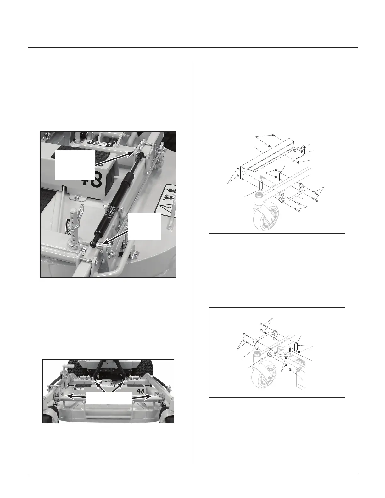
26. Mount the 10 mm Ball Stud, 5/16-18 x 3/4 (#18,
P/N 5155-13) on the LH Inner Pivot Plate (#10)
with three (3) 5/16 SAE washers (F049) and
secure with a 5/16-18 ange top lock nut
(F551). Mount the 10 mm Ball Stud, 5/16-18 x 1
(#34, P/N 5146-2) on the Lift Rod Weldment
(#1) with the spacer (#45, P/N 2720-3) another
F551 top lock nut. Install the gas spring on the
ball studs.
10 mm Ball
Stud (3/4”)
With Three
(3) Washers
10 mm Ball
Stud (1”)
With A
Spacer
Gas Spring Installed
27. Raise and lower the deck checking to make
sure the deck is level using the deck height pins
as a guide. They should all be within a 1/8” of
each other with the same number of holes
showing above the carrier frame. Lower and
raise the deck, and make sure the height still
matches the holes on the deck height pins.
Tighten the jam nuts on both control rods.
Pins All Even
Check Deck Levelness
28. If the height is not level on the deck height pins,
the Control Rods (#27) need to be adjusted
accordingly.
* Shorten the rods to lift the rear.
* Lengthen the rods to lower the rear.
NOTE: Height can only be adjusted front to
rear on each side respectively.
29. Install the LH guards using the hardware
shown. Do not overly tighten the bolts.
10
F569
F031
F398
F236
17
17
14
29
F569
F569
F569
LH Guards Illustration
30. Install the RH guards using the hardware
shown. Do not overly tighten the bolts.
NOTE: For decks prior to S/N 221298, it may
be necessary to drill out and deburr the guard
mount hole on the carrier frame to 5/16” before
installing the guard.
F236
F236
F569
F034
F569
F551
14
17
16
RH Guards Illustration