Assembly and Installation
7
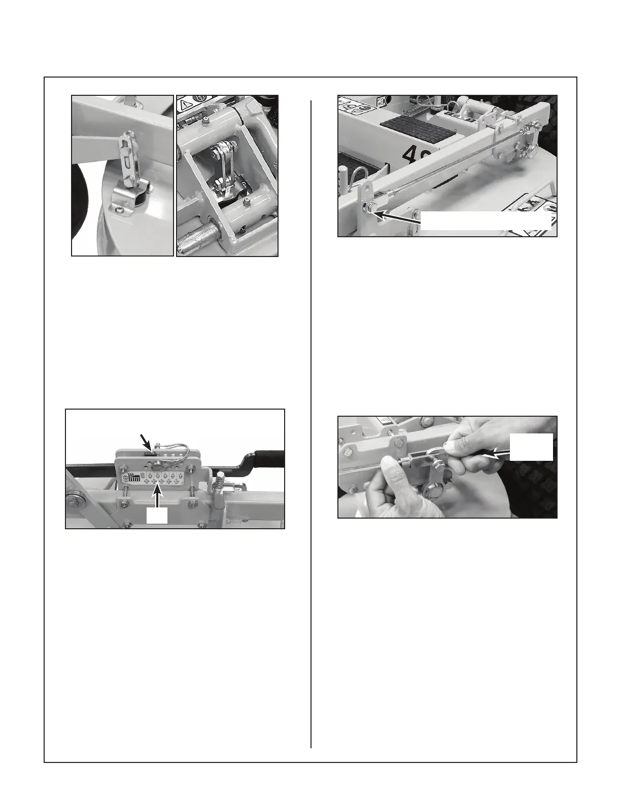
Front
Rear
Lift Links Secured (LH Shown)
19. Unblock the deck housing allowing it to rest on
the deck height pins and hitch pins.
20. Install the deck on a tractor.
21. Set the height on the deck height adjuster to 3”
using the Wire Lock Pin (#38, P/N 7775-3).
Make sure the Height Adjustment handle is
resting against the Wire Lock Pin.
Height Adjustment Handle Resting
Against Wire Lock Pin
3.0”
Deck Height Adjuster Set to 3”
22. On the LH side, install the Control Rod (#27,
P/N 5213-9) through the lower hole on the Lift
Rod Weldment (#1) and the slot on the Lift Arm
(#3 and #4) using a 5/16-18 x 1-1/16” hex bolt
(F706), a .745 x .320 x .125 washer (F603) and
a 5/16-18 ESNA LP nut (F288). Keep nger
tight.
F603 Washer On Outside
Install LH Control Rod
23. Adjust the length of the LH Control Rod so the
rear F706 mount bolt goes through the front of
the slot on the LH Lift Arm. Rotate the control
arm forward to remove any slack during this
step; there should be no slop between the F706
and the front of the slot. Once the length of the
rod is determined, twist the rear clevis fork one
time to shorten the rod. The bolt should no
longer reach the slot. Lift the deck housing to
slide the F706 mount bolt into the slot, and
secure the bolt. Fully tighten the front and rear
F288 nuts, but do not over tighten.
Push to
Rotate
Set Control Rod Length
24. Measure the length of the LH Control Rod, and
set the RH Control Rod to the same length
repeating the procedure to install the rod.
25. Carefully raise the deck using the deck lift pedal
to the highest setting and remove the hitch pins,
the spacer and the washer from the deck height
pins.