Assembly and Installation
6
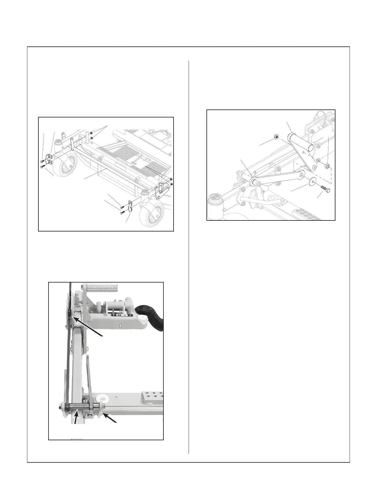
13. Install the Lift Rod Weldment (#1, P/N 7211-1)
along the front of the carrier frame using two (2)
Lift Rod Brackets (#21, P/N 7210-10) with a
5/16-18 x 3/4 hex bolt (F034) in the top hole
and a 5/16-18 x 1 hex bolt (F093) in the bottom
hole along with two (2) 5/16-18 ange top lock
nuts (F551). Fully tighten.
Install
F034
F551
F034
F093
F093
F551
1
21
21
Lift Rod Weldment
14. Install the Lifting Cross Tube assembly on the
Lift Rod Weldment using a 5/16-18 x 4 hex bolt
(F716) and a 5/16-18 ange top lock nut (F551).
Fully tighten.
Lift Handle Resting
Between Height Plate
and Pivot Plate
Lift Handle Resting
Between Height Plate
and Pivot Plate
Lifting Cross
Tube
Lifting Rod Weldment
Lifting Cross Tube Installed
15. Attach the Foot Pedal Link (#32) to the Foot
Pedal Arm (#33) using 5/16-18 x 1-1/8 hex bolt
(F645), 1.250 x .314 x .125 washer (F552), 5/8
x 5/16 x .280 spacer bushing (#23, P/N 6325-9),
and a 5/16-18 ange top lock nuts (F551). Fully
tighten.
F551
23
F645
F552
32
33
Attach Foot Pedal Arm to Foot Pedal Link
16. With the Height Adjustment Arm (#13) resting
between the Height Plate and RH Pivot Plate,
install the two (2) 1/4-20 x 1 hex bolts (F179)
and 1/4-20 ange top lock nuts (F569) in the top
holes with spacers (.5 x .250 x .438) (#24, P/N
6325-11) between the plates. Fully tighten re-
maining hardware on the height plate and the
RH pivot plates.
17. Install the carrier frame on the deck housing.
Block up the deck housing. Using the deck
height pins and hitch pins, set the deck height
to 3” with the washers and shims installed.
NOTE: The deck housing will still be resting on
blocks instead of the deck height pins at this
point.
18. Connect the four (4) sets of Lift Links to the
carrier frame using four (4) 1/4-20 x 13/16 hex
bolts (F705) and 1/4-20 LP nylock nuts (F350).
The Front Lift Links connect to the Lift Rod
Weldment (#1), and the Rear Lift Links (#20)
connect to the RH and LH Lift Arms (#3 and
#4). Tighten until snug; don’t over tighten. The
links must move freely.