WARN INDUSTRIES PAGE 3 70736A3
©2007 Warn Industries, Inc.
WARN® and the WARN logo are trademarks of Warn Industries Inc.
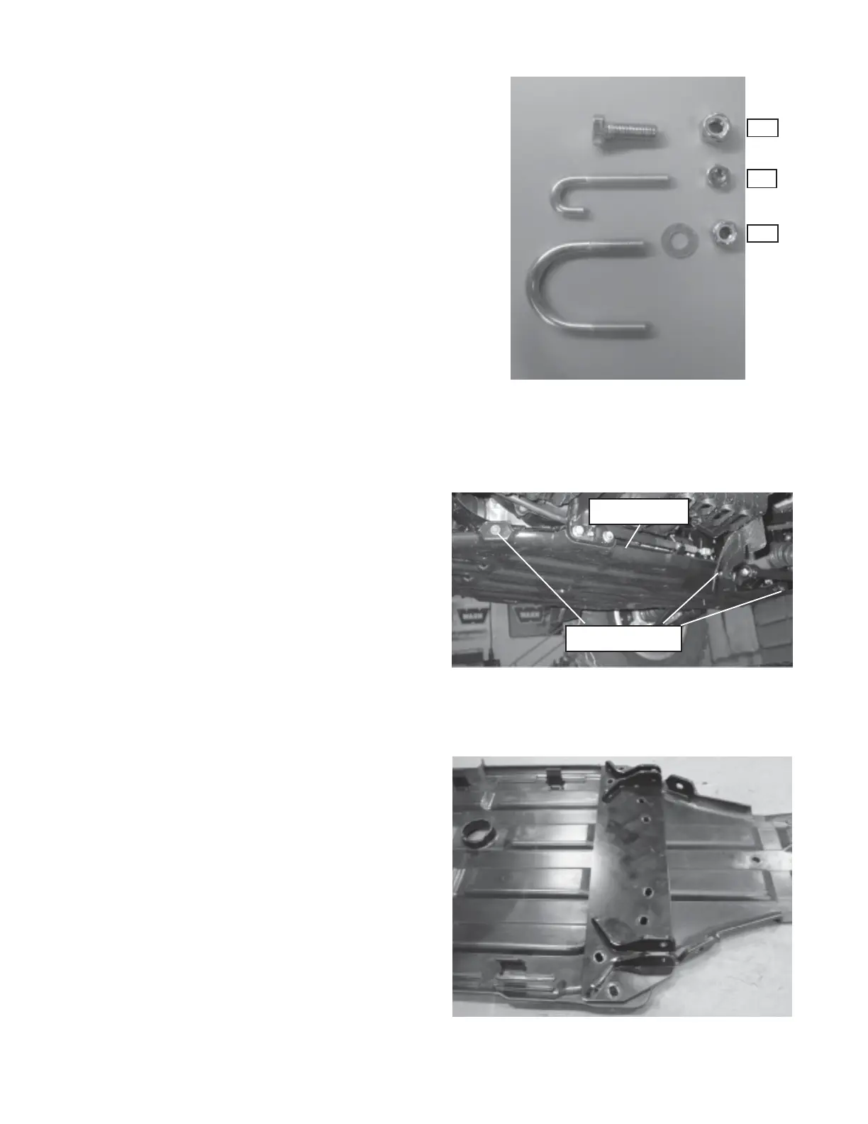
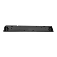
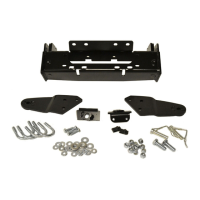
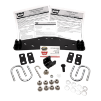
Figure 1
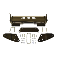
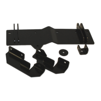
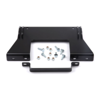
Figure 2
V. INSTALLATION
1. Install the plow mount using the fastener configura
tions as shown in Figure 1.
A. 3/8” Bolt, 3/8 Nylock Nut
B. J-Bolt, 1/4” Nut
C. 5/16” x 2.0” U-bolt, 5/16” Nylock Nut
2. To install the plow mount to the underside of the
vehicle, remove the factory skid plate. This will
require the use of a 10mm socket, as shown in Figure
2.
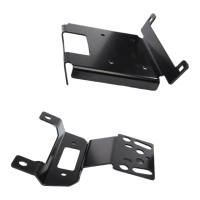
3. Once the skid plate is removed. Use the plow mount
as a template for holes to be drilled, as shown in figure
3.
Figure 3
Ax1
Bx2
Cx4
Skid Plate
Remove 6 Bolts
IV. FASTENER TORQUE SPECIFICATIONS
1/4 & M6 8 lb. ft. (10.8 N-m)
3/8 & M10 30 lb. ft. (40.7 N-m)
7/16 50 lb. ft. (67.8 N-m)
1/2 75 lb. ft. (101.7 N-m)
5/16 U-Bolt 11 lb. ft. (14.9 N-m)