23
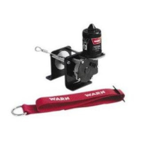
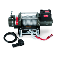
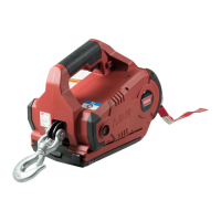
Figure 4.1a Figure 4.1b
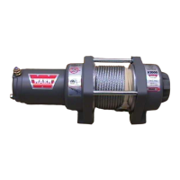
4.1.2 Contactor Control Pack- Electrical operation of this winch control
assembly consists of a contactor. Power to the remote control socket is supplied by the red wire
connected to a key controlled electrical wire from the ATV ignition. In the power out mode , the
black wire is triggered by the remote control switch to energize the control component.
In the power-in mode, the green wire is triggered by the remote control switch to energize the
control component.
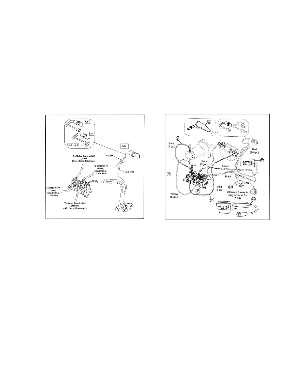
Figures 4.2a & b are the basic wiring diagram of the ATV winch contactor control pack .
Figure 4.2a Figure 4.2b
4.1.3 Solenoid Control Pack(winch)- For the power-in mode, the green
wire and the white wire are triggered by the remote control switch. For power out the black and
white wire are triggered by the remote.
Solenoids must be grounded and for each two solenoids the use of a diode is very necessary to
prevent any electrical danger. This diode will stop the winch in the event of electrical failure.
The diode wire is connected to solenoid and grounded to solenoid plate
Figure 4.3 is the basic wiring diagram of the ATV winch solenoid control pack .