6 Warner Electric • 800-825-9050 P-0257-WE • 819-9027
B. Panel Mounting
NOTE: Panel mount housings cannot be joined
together.
❑ 1. Insure the PC Board Assemblies have been
removed from the housings if installed by
loosening the two captive screws on the
front panels and sliding the assemblies out.
❑ 2. Using the dimensions shown in Figure 3,
page 6, cut an opening 3 5/16” x 6 1/16”
info the mounting panel for each housing
assembly.
❑ 3. Using the dimensions shown in Figures 3,
page 6, drill four (4) 13/64” mounting holes
for each housing to provide clearance for the
#10 mounting studs.
❑ 4. Slide the housing assemblies into the
mounting panel cutouts. Securely fasten the
housings to the mounting panel with the four
nuts on each housing.
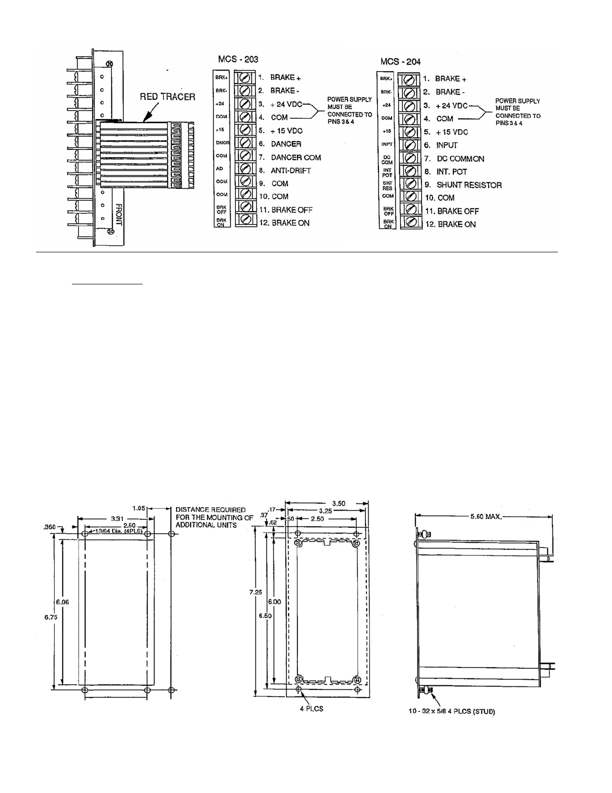
❑ 5. Apply the terminal strip label to the housing
panel near the terminal block as shown in
Figure 5, page 7.
CAUTION: Be sure to apply the label in the proper
position with the brake (+) terminal at
the top.
The controls are now ready to be wired. Proceed to
the wiring section of this manual for the appropriate
instructions.
Figure 3. Panel mount cut-out dimensions Figure 4. Panel mount housing dimensions
Figure 2. Terminal strip label orientation