This document is a maintenance manual for the Wärtsilä W-X62 "Marine" engine, identified by Document ID DBAD070428. It provides comprehensive information for the operation and maintenance of this specific diesel engine type.
Function Description:
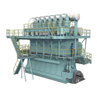
The Wärtsilä W-X62 is a marine diesel engine designed for propulsion and power generation in marine applications. The manual covers various engine components and systems, including the bedplate, tie rods, cylinder liners, cylinder covers, crankshaft, connecting rods, pistons, driving wheels, starting air shut-off valve, supply unit, injection and exhaust valve control, scavenge air receiver, auxiliary blower, cylinder lubrication, piping, and crank angle sensor unit. The engine is designed to operate with turbochargers (Turbocharger 1 and Turbocharger 2) and auxiliary blowers (Auxiliary Blower 1 and Auxiliary Blower 2) to enhance performance. It features a cylinder numbering system (1 through 6 or 1 through 8 depending on the configuration shown in the diagrams) and main bearing numbering. The manual also illustrates the driving end, free end, fuel side (with a rail unit and supply unit), and exhaust side of the engine. Rotation can be counterclockwise or clockwise.
Important Technical Specifications:
The manual includes several tables and sections dedicated to technical specifications crucial for maintenance. These include:
- Clearance Table (0330-1/A1): This section provides normal and maximum acceptable clearances for various engine components, such as the crankshaft and thrust bearing (pages 2, 3), crankshaft and main bearing (pages 4, 5), crosshead guide (pages 6, 7), cylinder liner (pages 8, 9), piston rod gland (pages 10, 11), exhaust valve (pages 12, 13), top and bottom end bearings to connecting rod (pages 14, 15), piston cooling and crosshead lubricating link (pages 16, 17), piston and piston rings (pages 18, 19), driving wheels for supply unit (pages 20, 21), fuel and servo pump units (pages 22, 23), and fuel pump (pages 24, 25).
- Tightening Values of Important Screwed Connections (0352-1/A1): This section details the required tightening values for critical bolted connections throughout the engine.
- Torque Values and Elastic Stud Replacement - Standard Screws and Elastic Studs (0352-2/A1): Provides specific torque values and procedures for replacing standard screws and elastic studs.
- Masses (Weights): Individual Components per Piece in kg (0360-1/A1): Lists the weights of individual engine components, which is essential for safe lifting and handling during maintenance.
- Engine Cross Section and Longitudinal Section (0803-1/A1): Offers detailed diagrams of the engine's internal structure.
Usage Features:
The manual emphasizes the importance of using original spare parts and components to ensure satisfactory engine operation. All equipment and tools for maintenance and operation must be serviceable and in good condition. The scope of supplies and services is determined by the related supply contract. The manual also highlights that information regarding the operation of the engine and descriptions of various systems are provided in a separate "Operating Manual."
Maintenance Features:
The W-X62 maintenance manual is structured to guide personnel through various maintenance tasks. Key maintenance features include:
- General Guidelines (0011-1/A1, 0012-1/A1): Covers safety measures and warnings for maintenance, and guidelines for lifting tools such as wire rope slings, span-sets, and eye bolts.
- Maintenance Schedule: Inspection and Overhaul Intervals (Guidelines) (0380-1/A1): This critical section provides nominal intervals for various maintenance operations, based on experience and standard operating conditions. Updates to overhaul times for injection valves are noted (e.g., 0380-1/A1 (2) in 2014-08).
- Detailed Instructions by Design Group: The manual is divided into main chapters or "Design Groups" (0-9) that provide detailed instructions for maintenance work on specific engine parts.
- Group 0: General Information (as described above).
- Group 1: Bedplate and Tie Rod (e.g., checking foundation bolts, main bearing removal/fitting, thrust bearing axial clearance, engine stays, tie rod pre-tension).
- Group 2: Cylinder Liner and Cylinder Cover (e.g., measuring bore wear, removal/fitting of liners and covers, re-dressing lubricating grooves, injection valve replacement/disassembly/checks, starting air valve maintenance, relief valve blow-off pressure check, exhaust valve removal/installation/grinding).
- Group 3: Crankshaft, Connecting Rod and Piston (e.g., measuring crank deflection, vibration damper inspection, axial damper disassembly, turning gear checks, connecting rod bearing removal/inspection, crosshead clearance checks, piston removal/disassembly/checks, piston ring wear).
- Group 4: Driving Wheels and Shut-off Valve for Starting Air (e.g., running/backlash clearances, tooth condition, cleaning/function check of shut-off valve).
- Group 5: Supply Unit, Injection and Exhaust Valve Control (e.g., fuel pump disassembly/assembly, fuel pressure control valve, PCV relief valve, camshaft/bearing shells, fuel pump actuator, servo oil pump, servo oil rail, exhaust valve control unit).
- Group 6: Scavenge Air Receiver and Auxiliary Blower (e.g., cleaning/checks of receiver, blower maintenance, cooler removal/installation, water separator, waste gate).
- Group 7: Cylinder Lubrication (e.g., cylinder lubricating system).
- Group 8: Piping (e.g., exhaust waste gate, HP servo oil pipe, hydraulic pipe for exhaust valve drive, HP fuel pipe removal/grinding/installation).
- Group 9: Crank Angle Sensor Unit, Tools (e.g., replacement of proximity sensor, explanation of tools, hydraulic pre-tensioning jacks and pumps, tool list including standard and recommended special tools).
- Tool Lists (9403-5/A1): Describes the tools and devices necessary for maintenance, which are generally supplied with the engine. Updates include new pipe grinding tools (94841, 94871, 94870) and new tool numbers for T/C Covers.
- Modification Service: The manual includes a "Summary for Maintenance Manual" section (page 3) that lists modifications and updates to the manual, indicating the date of publication for these changes (e.g., 2014-06-02, 2014-09-18). This ensures users have the most current information.
- Personnel Qualification: Emphasizes that only qualified personnel with applicable knowledge and training should perform work on the engine and its systems.
- Confidentiality: The publication is confidential and intended for information purposes only. Wärtsilä Switzerland Ltd. assumes no liability for direct, indirect, special, incidental, or consequential damages related to the information contained herein.