EasyManua.ls Logo

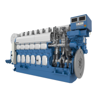
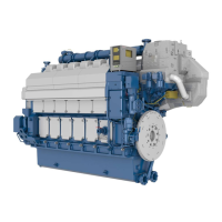
Wartsila VASA 6L32 User Manual

Wartsila VASA 6L32
394 pages
To Next Page IconTo Next Page
Page #1 background imageLoading...
Page #1 background image
Document ID
Installation
Engine type VASA 6L32
Engine number
PAAE051728
Project
This manual is intended for the personal use of engine operators
and
should always be at their disposal. The content of this manual
shall neither be copied nor communicated to a third person.
Wärtsila Finland Oy
Vaasa Factory
Tarhaajantie 2, FIN-65101 Vaasa, Finland
Tel. +358 10 709 0000, Tlx 74251 wva sf
Fax (Service) +358 6 356 7355
Fax (Spare Parts) +358 10 709 1380
INSTRUCTION MANUAL

Questions and Answers:

Wartsila VASA 6L32 Specifications

General IconGeneral
Cylinder ArrangementIn-line
Number of Cylinders6
Bore320 mm
Stroke400 mm
Speed750 rpm
Fuel TypeHeavy Fuel Oil (HFO)
Fuel Consumption178 g/kWh
Engine Type4-stroke diesel engine

Summary

00. Contents, Instructions, Terminology

00.1 Contents of the Manual

Provides an overview of the manual's content and purpose, assuming basic engine knowledge.

00.2 General rules

Outlines essential rules for handling the engine and performing maintenance work.

00.3 Terminology

Defines key terms used in the manual, including engine orientation and cylinder designation.

00A. Risk Reduction

00A.1 General

Lists general identified hazards and hazardous situations during normal operation and maintenance.

01. Main Data, Operating Data and General Design

01.1 Main data for Wärtsilä 32

Details essential specifications like cylinder bore, stroke, and oil/water volumes for Wärtsilä 32 engines.

01.2 Recommended operating data

Provides normal values and alarm limits for temperatures and pressures during engine operation.

01.3 Reference conditions

Specifies reference conditions (air pressure, temperature, humidity) for engine performance evaluation.

01.4 General engine design

Describes the engine's construction, including block, crankshaft, liners, bearings, and connecting rods.

02. Fuel, Lubricating Oil, Cooling Water

02.1 Fuel

Details general information on fuel types, viscosity limits, and handling requirements for Wärtsilä engines.

02.1.2 Fuel treatment

Explains the purification process for heavy fuel, including recommended temperatures and flow rates for centrifuging.

02.2 Lubricating oil

Outlines system oil characteristics, including viscosity, VI, and alkalinity (BN) requirements tied to fuel type.

02.3 Cooling water

Specifies general requirements for cooling water treatment, additives, and quality to prevent corrosion.

02A. Environmental Hazards

02A.1 General

Highlights that fuel oils, lubricating oils, and cooling water additives are environmentally hazardous.

02A.2 Fuel oils

Details hazards associated with fuel oils, including skin irritation, fumes, fire risk, and environmental contamination.

02A.4 Lubricating oils

Discusses hazards of fresh and used lubricating oils, emphasizing skin contact prevention and environmental contamination.

04. Maintenance Schedule

04.1 General

States that operating conditions and fuel quality determine maintenance needs; schedule periods are guidance only.

04.4 Interval: 50 operating hours

Details checks required at 50 operating hours, including tightening of screws and oil levels.

04.6 Interval: 500 operating hours

Lists tasks for 500 operating hours, such as checking water quality and taking oil samples.

05. Maintenance Tools

05.1 General

Explains the purpose and selection of special tools developed for Wärtsilä engines.

06. Adjustments, Clearances and Wear Limits

06.1 Adjustments

Details valve timing adjustments, clearances, and fuel delivery commencement settings.

06.2 Clearances and wear limits (at 20°C)

Provides normal and wear limit clearances for various engine parts like bearings, liners, and rings.

07. Tightening Torques and Use of Hydraulic Tools

07.1 Tightening torques for screws and nuts

Lists tightening torques for various screws and nuts, with reference to figures and specific notes.

07.3 Hydraulically tightened connections

Details hydraulic tightening pressures and cylinder specifications for various connections.

07.3.4 Dismantling hydraulically tightened screw connections

Provides step-by-step instructions for safely dismantling hydraulically tightened screw connections.

08. Operating Troubles, Emergency Operation

08.1 Trouble shooting

Offers guidance on identifying and resolving common engine operating troubles and their possible causes.

08.2 Emergency operation

Describes procedures for operating the engine with defective components like air coolers or turbochargers.

10. Engine Block with Bearings, Oil Sump and Cylinder Liner

10.3 Main bearings

Outlines the procedure for dismantling and assembling main bearings, including the use of hydraulic tools.

11. Crank Mechanism: Crankshaft, Connecting Rod, Piston

11.2 Crankshaft alignment

Describes the process for checking crankshaft alignment on a warm engine using a transducer.

11.3.3 Changing of big end bearings

Provides instructions for changing big end bearings, including removal and reassembly steps.

11B. Piston Overhaul

11B.1 General

States that engines use composite pistons and require extensive inspections during overhaul.

11B.3 Piston crown

Covers visual inspection, crack detection, and measurements for piston crowns.

11B.4 Piston skirt

Details visual inspection, support surface assessment, and crack detection for piston skirts.

12. Cylinder Head with Valves

12.1 General description

Describes the cylinder head's construction, including valves, injection valve, and cooling passages.

12.3 Exhaust and inlet valves and seat rings

Details the general description of valves, seat rings, and their dismantling procedures.

12.3.3 Checking and reconditioning of valves and seats

Explains how to check and recondition valves and their seats, including machine grinding.

12A. Testing of cylinder tightness

12.A.1 Testing

Describes the procedure for testing cylinder and valve tightness using a specialized tool.

13. Camshaft Driving Gear

13.2 Intermediate gears and camshaft gear

Covers maintenance and basic adjustment of valve timing for intermediate gears and camshaft.

14. Valve Mechanism and Camshaft

14.1 Valve mechanism

Details the valve mechanism's operation, lubrication, and maintenance requirements.

14.2 Camshaft

Describes the camshaft's construction, driving mechanism, and removal/mounting procedures.

15. Turbocharging and Air Cooling

15.2 Turbocharger maintenance

Outlines the procedures for turbocharger maintenance, emphasizing the use of new seals during reassembly.

15.3 Water cleaning of turbocharger during operation

Describes methods for cleaning the turbocharger's turbine and compressor sides using water.

15.5 Charge air cooler

Covers general maintenance, dismantling, pressure testing, and assembling of the charge air cooler.

16. Injection System

16.1 Injection pump

Provides a general description of the injection pump, its multihousing functions, and components.

16.2 Maintenance of injection pump

Outlines operations for injection pump maintenance, including removal and mounting procedures.

16.4 Injection valve

Details the injection valve's description, removal, overhauling, and testing procedures.

17. Fuel System

17.1 General

Describes the fuel system's design for continuous operation on various fuel types and the importance of fuel treatment.

17.4 Adjustments of fuel feed system

Covers adjustments for fuel feed pumps, circulating pumps, and feed pressure at each engine.

18. Lubricating Oil System

18.1 General design

Details the lubricating oil system's design, including the pump, cooler, filters, and oil flow paths.

18.2 General maintenance

Emphasizes using approved oils, maintaining oil levels, and performing regular oil changes with utmost cleanliness.

18.3 Lubricating oil pump

Outlines the description, removal, dismantling, inspection, and assembly of the lubricating oil pump.

18.5 Lubricating oil cooler

Covers the description, general maintenance, and disassembly/assembly procedures for the lubricating oil cooler.

18.7 Lubricating oil automatic filter

Details the filter's description, maintenance, filter candle inspection, and cleaning.

18.8 Centrifugal filter

Describes the centrifugal filter and its cleaning procedure, emphasizing regular cleaning.

19. Cooling Water System

19.1 Description

Details the engine's cooling system, divided into HT and LT circuits, and the function of temperature control valves.

19.2 Maintenance

Outlines general maintenance procedures, emphasizing adherence to manufacturer instructions and cooling water treatment.

19.3 Water pump

Describes the water pump's construction, driven by gear mechanism, and its maintenance procedures.

20. Exhaust System

20.1 Exhaust manifold

Details the exhaust manifold's construction, consisting of multiducts, exhaust pipes, and bellows.

21. Starting Air System

21.1 Description

Describes the starting air system, its components, pressure requirements, and manual/remote operation.

21.2 Main starting valve

Explains the main starting valve's construction, manual/pneumatic operation, and maintenance.

21.7 Slow turning device

Explains the slow turning device system for engine rotation before starting and its settings.

22. Control Mechanism

22.1 Description

Details the governor's role in engine speed control and the transfer of regulation movement.

22.2 Maintenance

Emphasizes paying special attention to system function to prevent overspeeding or load issues.

22.5 Electro-pneumatic overspeed trip device

Explains the device's function, check/adjustment of stop position, and tripping speed check.

23. Instrumentation and Automation

23.1 General

Introduces the Wärtsilä Engine Control System (WECS 2000) for monitoring and control.

23.2 Functional description

Details WECS functions including speed measuring, safety systems, and shutdown procedures.

23.5 Hardware

Covers the WECS hardware units, including MCU Frame, Mother Board, DC/DC Converter, and Interface Boards.

23.7 Maintenance and Troubleshooting

Provides information on controls, indicators, and troubleshooting procedures for WECS components.

23.7.2 Controls and Indicators

Details controls and indicators for the MCU, including LED functions on various boards.

Related product manuals