Do you have a question about the Wartsila WARTSILA32 and is the answer not in the manual?
Provides rating tables for Wärtsilä 32 engines at different configurations and speeds.
Specifies standard ambient conditions for engine output and fuel consumption.
Details maximum allowable inclination angles for satisfactory engine operation.
Outlines special arrangements for cold ambient air conditions and engine operation.
Presents dimensional data and weights for in-line and V-engines, and generating sets.
Describes engine operation modes, including IMO Tier 2 and SCR modes.
Explains engine operating limits, including shaded areas for temporary operation.
Covers controlled load increase for supercharged diesel engines and pre-heating requirements.
Provides recommendations for operating on heavy fuel at low load and idling.
Specifies minimum inlet air temperatures for cold conditions and arctic operation.
Presents detailed technical specifications for the Wärtsilä 6L32 engine at 720 rpm.
Provides detailed technical specifications for the Wärtsilä 6L32 engine at 750 rpm.
Presents detailed technical specifications for the Wärtsilä 8L32 engine at 720 rpm.
Provides detailed technical specifications for the Wärtsilä 8L32 engine at 750 rpm.
Presents detailed technical specifications for the Wärtsilä 9L32 engine at 720 rpm.
Provides detailed technical specifications for the Wärtsilä 12V32 engine at 720 rpm.
Presents detailed technical specifications for the Wärtsilä 12V32 engine at 750 rpm.
Provides detailed technical specifications for the Wärtsilä 16V32 engine at 720 rpm.
Presents detailed technical specifications for the Wärtsilä 16V32 engine at 750 rpm.
Defines terms and provides diagrams for in-line and V-engine configurations.
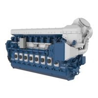
Describes key engine components and systems like the engine block, crankshaft, connecting rod, etc.
Provides detailed cross-section diagrams of the in-line and V-engines.
Lists overhaul intervals and expected life times for engine components based on HFO usage.
Provides guidance on engine storage, including VCI coating and tarpaulin.
Outlines factors to consider when selecting pipe dimensions, including material and pressure loss.
Describes how classification societies categorize piping systems based on media, pressure, and temperature.
Provides instructions for treating, cleaning, and protecting piping systems.
Provides guidelines for the proper installation of flexible pipe connections.
Offers guidelines for fixing pipes to rigid structures to prevent vibration damage.
Outlines fuel specifications based on ISO 8217:2012 standard and fuel properties.
Illustrates the internal fuel oil system for in-line and V-engines, detailing components and pipe connections.
Discusses the design of external fuel systems, including treatment, separators, and tanks.
Shows example fuel feed systems for HFO installations, detailing components and pipes.
Specifies requirements for lubricating oil, including viscosity class and Base Number (BN).
Illustrates the internal lubricating oil system for in-line engines, detailing components and sensors.
Shows lubricating oil systems for main and auxiliary engines, including components and pipe connections.
Offers guidance on flushing procedures for piping and equipment.
Specifies the required quality standards for instrument air used in safety and control devices.
Describes the use of compressed air for engine starting and its system requirements.
Discusses the design of external starting air systems, including capacity and pipe inclination.
Specifies the required quality parameters for fresh water in the cooling system, including pH, hardness, and chlorides.
Illustrates internal cooling water systems for in-line and V-engines, detailing components and sensors.
Presents example diagrams for external cooling water systems for main engines.
Discusses considerations for cooling water systems in arctic conditions, focusing on air temperature effects.
Stresses the requirement for preheating cooling water to at least 60°C, especially for heavy fuel.
Emphasizes the importance of engine room ventilation for acceptable operating conditions and trouble-free operation.
Covers the design of the combustion air system, including filters and fans.
Addresses combustion air system design for arctic conditions, considering cold air effects.
Illustrates the internal exhaust gas system for in-line engines, detailing components and pipe connections.
Shows diagrams and tables for exhaust pipe connections and configurations for in-line and V-engines.
Discusses external exhaust gas system design, including piping, supporting, and back pressure.
Compares conventional and Compact Silencer System (CSS) technologies for exhaust gas silencing.
Explains the regular water cleaning process for turbine and compressor deposits using a dosing unit.
Lists the primary components of diesel engine exhaust emissions and their formation.
Covers marine exhaust emissions regulations, focusing on IMO.
Explains primary and secondary methods for reducing exhaust emissions.
Describes UNIC C2 as a modular embedded automation system with hardwired and bus interfaces.
Covers engine starting procedures, startblockings, and shutdown functions.
Refers to P&I diagrams and project-specific documentation for signal configurations.
Discusses motor starters for pumps and operation of electrically driven pumps.
Covers steel structure design for foundations, oil tanks, and the importance of stiffness.
Discusses methods for mounting main engines, including rigid and resilient options.
Covers the mounting of generating sets, including generator feet design and resilient mounting.
Provides guidelines for flexible pipe connections when engines are resiliently installed.
Lists external forces and couples produced by some cylinder configurations for ship designer's reference.
Presents tables showing torque variations at different loads and speeds.
Explains how airborne noise is measured and presents sound power level data.
Shows typical sound power levels for engine and exhaust noise.
Discusses the use of flexible couplings for power transmission from engines to generators or propulsion.
Recommends multiple plate hydraulically actuated clutches for separating the propeller shaft.
Emphasizes the need for a shaft locking device to prevent propeller shaft movement and bearing wear.
Lists required data for torsional vibration calculations for shaft systems.
Specifies minimum crankshaft distances between engines for maintenance and operation.
Covers space requirements around the engine for maintenance and component removal.
Outlines transportation arrangements for heavy engine components and storage recommendations.
Mentions the need for deck area during engine overhaul for cleaning and component storage.
Provides diagrams and tables for lifting dimensions and weights of in-line main engines.
Shows lifting dimensions and weights for generating sets.
Lists weights and dimensions for major engine components like turbochargers and coolers.
Provides tables for converting units used in the document, such as length, pressure, power, and temperature.
Presents a list of standard symbols used in technical drawings within the document.
| Bore | 320 mm |
|---|---|
| Stroke | 400 mm |
| Cooling System | Water-cooled |
| Displacement per cylinder | 32.2 liters |
| Speed | 720 or 750 rpm |
| Fuel Type | Heavy fuel oil, Marine diesel oil |
| Emission compliance | IMO Tier II |
| Weight | Varies depending on the number of cylinders and configuration |
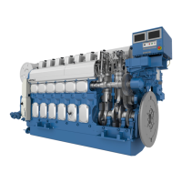
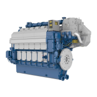
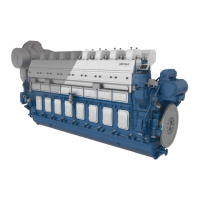
| Type | Four-stroke, medium-speed diesel engine |




 Loading...