Do you have a question about the Wartsila 46F Series and is the answer not in the manual?
Details the maximum continuous output capabilities of the Wärtsilä 46F engine.
Provides detailed dimensions and weights for in-line and V-engines.
Describes the engine's operational limits, including speed and load conditions.
Details controlled load increase for supercharged engines and loading ramps.
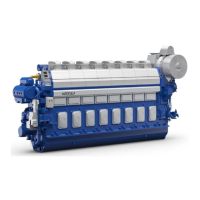
Presents detailed technical specifications for the Wärtsilä 6L46F engine.
Details technical specifications for the Wärtsilä 12V46F engine.
Outlines technical specifications for the Wärtsilä 16V46F engine.
Describes the main components and systems of the Wärtsilä 46F engine.
Details the fuel injection system, including pumps, nozzles, and timing control.
Describes the dry oil sump and standard lubricating oil system configuration.
Describes the Wärtsilä Unified Controls (UNIC) automation system for engine management.
Provides a cross-section view of the in-line engine for visual understanding.
Factors to consider when selecting pipe dimensions, including material and velocity.
Details cleaning procedures for piping systems before delivery and installation.
Offers guidelines for proper installation of flexible pipe connections to prevent damage.
Details acceptable fuel specifications based on ISO 8217 and additional properties.
Illustrates the internal fuel oil system for in-line and V-engines with component descriptions.
Outlines design considerations for external fuel oil systems, including cleaning and circulation.
Explains the necessity of centrifugal separators for heavy fuel cleaning and their operation.
Specifies requirements for engine lubricating oil, including viscosity and Base Number (BN).
Illustrates the internal lubricating oil system for in-line and V-engines.
Depicts external lubricating oil systems with engine-driven and electric pumps.
Explains the mandatory operation of the pre-lubricating oil pump for engine safety.
Outlines the quality requirements for instrument air used in safety and control devices.
Describes the internal compressed air system, including starting and control functions.
Details the design of the starting air system, including receivers and compressors.
Specifies the fresh water quality requirements for the engine cooling water system.
Illustrates the internal cooling water systems for in-line and V-engines.
Depicts external cooling water systems for single and multiple engine installations.
Emphasizes the requirement for preheating cooling water, especially for HFO operation.
Details engine room ventilation requirements for maintaining acceptable operating conditions.
Explains the design considerations for the combustion air system, including filters and fans.
Illustrates the internal exhaust gas system, including turbocharger and air cooler.
Covers design factors for external exhaust systems, including piping, support, and backpressure.
Discusses exhaust gas silencing options and compares silencer systems.
Details the automatic turbocharger cleaning system, including components and water supply.
Explains the main components of diesel engine exhaust emissions, including NOx and SOx.
Covers IMO Tier 3 NOx emission standards and their implementation timeline.
Discusses primary and secondary methods for reducing diesel engine exhaust emissions.
Describes the UNIC C2 system, its architecture, and communication protocols.
Explains key engine functions like starting, stopping, and speed control.
Provides guidelines for propulsion control and power management systems in diesel-electric ships.
Details requirements for the steel structure design of the foundation to absorb dynamic forces.
Explains engine mounting methods, including rigid and resilient options.
Explains rigid engine mounting using steel or resin chocks and holding down bolts.
Explains resilient engine mounting on steel spring elements to reduce vibrations.
Lists dynamic forces and couples produced by certain cylinder configurations.
Presents typical sound power levels of engine airborne noise in octave bands.
Shows typical sound power levels of exhaust noise in octave bands.
Recommends hydraulically operated multi-plate clutches and their requirement in twin screw vessels.
Details shaft locking devices to prevent propeller windmilling and for maintenance safety.
Describes the engine's turning gear and situations requiring higher torque capacity.
Specifies minimum crankshaft distances for sufficient space between engines.
Recommends minimum free space around the engine for maintenance operations.
Provides detailed service space requirements for the in-line engine, including component access.
Shows lifting points and provides weights for in-line engines without flywheel.
Illustrates lifting of V-engines and provides dimensions and weights.
Provides tables for converting units used throughout the product guide.