Do you have a question about the Wartsila 34DF Series and is the answer not in the manual?
Engine bore, stroke, displacement, valve count, configuration, rotation, speed, and piston speed.
Rating table for Wärtsilä 34DF engines and generating sets, with formula for mean effective pressure.
Derating due to methane number, charge air temperature, gas feed pressure, and LHV.
Ambient conditions for output specification and fuel consumption, referencing ISO standards.
Maximum inclination angles for satisfactory engine operation.
Dimensions and weights for main engines (in-line, V) and generating sets.
Limits for engine operation below nominal speed, transient operation, and minimum speed.
Importance of controlled load increase for supercharged engines, loading ramps, and overload capabilities.
Restrictions and guidelines for low load and idling engine operation.
Minimum inlet air temperatures for gas and diesel modes in cold conditions.
Technical data for 6-cylinder in-line engine: combustion air, exhaust gas, heat balance, fuel, and lube oil systems.
Technical data for 9-cylinder in-line engine: combustion air, exhaust gas, heat balance, fuel, and lube oil systems.
Technical data for 12-cylinder V-engine: combustion air, exhaust gas, heat balance, fuel, and lube oil systems.
Technical data for 16-cylinder V-engine: combustion air, exhaust gas, heat balance, fuel, and lube oil systems.
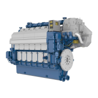
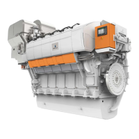
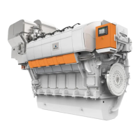
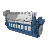
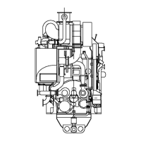
Definitions of in-line and V-engine configurations with diagrams.
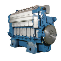
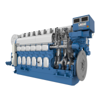
Overview of engine parts like block, crankshaft, connecting rods, bearings, cylinder liners, pistons, heads, camshaft, fuel, exhaust, lube oil, cooling, turbocharging, automation systems.
Detailed cross-section diagrams of in-line and V-engines.
Table detailing time between overhauls and expected component lifetimes for different operations.
Guidelines for selecting pipe dimensions considering material, pressure loss, NPSH, and velocity.
Pipes requiring trace heating (heavy fuel, leak fuel, filter flushing) for heat retention.
Criteria for selecting piping pressure class based on design, operating pressure, and safety valves.
Classification of piping systems by DNV rules based on media, pressure, and temperature.
Guidelines for cleaning piping systems and equipment before installation.
Requirements for proper installation of flexible pipe connections to prevent damage.
Guidelines for fixing pipes to rigid structures to prevent vibration damage.
Gas fuel specifications including LHV, methane number, and contaminants.
Specifications for Marine Diesel Fuel (MDF) grades like DMX, DMA, DMZ, and DMB.
Engine operation on liquid bio fuels and biodiesel specifications.
Dual fuel engine operation modes (gas, diesel, backup) and mode change principles.
Internal fuel gas system components, sensors, and pipe connections.
External fuel gas system design, double wall piping, ventilation, and gas valve unit.
Internal fuel oil system diagrams and components for in-line and V-engines.
External fuel oil system design, cleaning, viscosity, and heating requirements.
Fuel tank arrangements including bunker, settling, and day tanks.
Procedures for fuel treatment, primarily separation using centrifugal separators.
Operating modes for separators based on fuel density and disc type.
Design data for separator feed pumps, including capacity and pressure.
Design and requirements for separator preheaters to maintain fuel temperature.
Example of a fuel oil system for MDF installations with diagrams.
Example of HFO fuel oil system with diagrams for multiple engine installations.
Procedures for starting and stopping engines on HFO and MDF, including system flushing.
Sequence and equipment for changing fuel from HFO to MDF, ensuring smooth transfer.
Description of a completely assembled feeder/booster unit and its equipment.
Requirements for engine lubricating oil, including viscosity and Base Number (BN).
Diagrams and components of the internal lubricating oil system for in-line engines.
Diagrams and components of external lubricating oil systems for wet and dry oil sumps.
Requirements for lubricating oil separators, including dimensioning for continuous separation.
Purpose and requirements for crankcase ventilation pipes and condensate traps.
Flushing requirements for piping and equipment built on the engine.
Flushing procedures for external oil systems, including tanks and pipes.
Recommendations for flushing oil viscosity and types (engine oil vs. flushing oil).
Requirements for instrument air quality, including pressure, dew point, oil, and particle content.
Engine starting system using compressed air, including slow turning and non-return valves.
Design of starting air systems, including receivers, compressors, and piping inclinations.
Dimensioning and requirements for starting air vessels, including condensate drain.
Importance and installation of starting air filters to prevent particle entry.
Requirements for fresh water quality in the cooling water system, including pH and contaminants.
Diagrams and components of the internal cooling water systems for in-line engines.
Information on engine-driven HT and LT cooling water pumps and their curves.
Diagrams and components of external cooling water systems for in-line engines.
Control of charge air temperature using an external LT circuit valve.
Function and design data for expansion tanks in cooling systems.
Requirement for preheating cooling water, especially for heavy fuel operation.
Requirements for engine room ventilation and combustion air supply, including heat emission calculation.
Design considerations for combustion air systems, including fan selection and ducting.
Optional charge air shut-off valve for preventing flammable gas ingestion.
Estimation of condensed water in charge air coolers, especially in tropical conditions.
Diagrams and components of the internal exhaust gas system for in-line and V-engines.
Exhaust pipe connections, diameters, and supports for different engine types.
Design factors and safety aspects for external exhaust gas systems.
Installation of explosion relief devices (rupture discs) in the exhaust system.
Proper fixing and support of exhaust pipes to prevent vibration damage.
Installation requirements for SCR units and exhaust gas boilers.
Typical dimensions and noise attenuation of exhaust gas silencers.
Description of the turbocharger water cleaning system, including dosing unit and water supply.
Cleaning of the turbocharger compressor side using the same equipment as the turbine.
Typical exhaust emissions for dual fuel engines in gas mode, including NOx and CO2 levels.
Overview of IMO regulations (MARPOL Annex VI) for marine exhaust emissions.
Primary and secondary methods for reducing diesel engine exhaust emissions.
Description of the UNIC C3 automation system, its architecture, and modules.
Functions and features of the engine safety system, including hardwired logic and redundancy.
Overview of engine operating modes and control system functions.
Functions related to engine start-up, including start blocking conditions.
Procedures for transferring between gas and diesel operating modes.
Procedures for stopping, shutting down, and emergency stopping the engine.
Electronic speed control for main engines and generating sets.
Design considerations for steel structures supporting the engine and oil tank.
Methods for mounting main engines, including rigid and resilient options.
Principles and arrangements for resilient engine mounting using rubber elements.
Mounting procedures for generating sets, including generator feet design.
Requirements for flexible pipe connections when resiliently installing engines/sets.
External forces and couples produced by some cylinder configurations, with tables.
Table showing torque variations at 100% load for different engines.
Measurement of airborne noise using sound power level according to ISO 9614-2.
Typical sound power levels for exhaust noise for W L34DF and W V34DF.
Types of flexible couplings for power transmission and torsional vibration calculations.
Installation of torque meters using torque flanges for measuring absorbed power.
Use of clutches, especially multiple plate hydraulic clutches, for separating propeller shafts.
Importance and types of shaft locking devices for maintenance and preventing wind milling.
Availability and verification of engine power take-off from the free end.
Required data for torsional vibration calculations, covering installation, reduction gear, propeller, generator, and couplings.
Description of the engine's electrical driven turning gear for flywheel rotation.
Minimum crankshaft distances for maintenance and operation of in-line and V-engines.
General requirements for working space around the engine and lifting equipment.
Guidelines for transporting and storing heavy engine components and spare parts.
Deck area requirements for engine overhaul activities.
General guidelines for father-and-son engine arrangements, considering component access and platforms.
Ensuring free space for maintenance around adjacent shafts and covering them.
Diagrams and dimensions for lifting main engines (in-line and V-engines).
Diagrams and dimensions for lifting generating sets.
Dimensions and weights for major engine components like lubricating oil inserts and charge air coolers.
Tables for converting units used in the guide, such as length, pressure, power, and flow.
Common prefix multipliers used in scientific and engineering notation.
A collection of symbols used in technical drawings with their meanings.
