11. Exhaust Gas System
11.1 Internal exhaust gas system
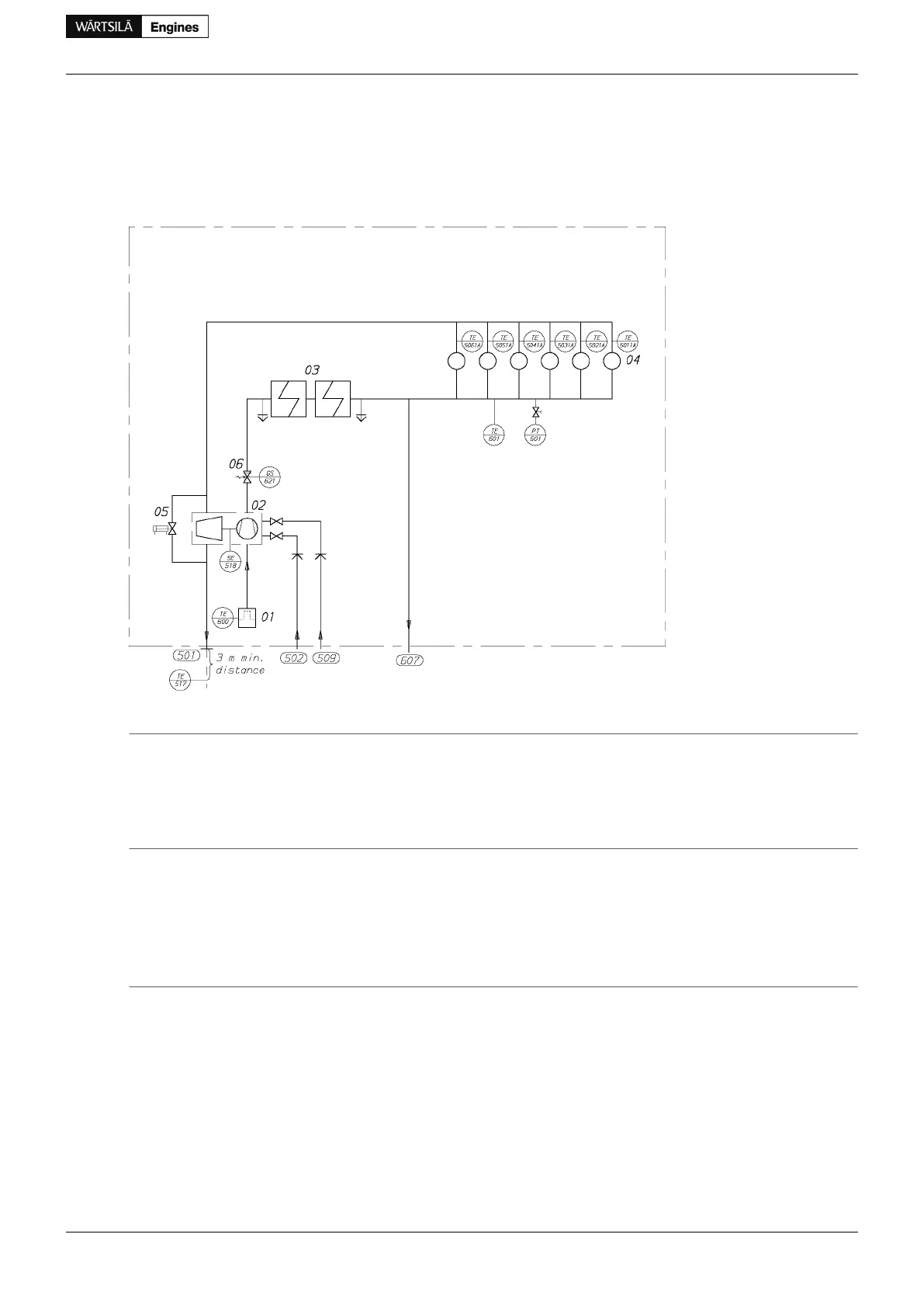
Figure 11.1 Charge air and exhaust gas system, in-line engines (DAAE055614a)
System components
Cylinder04Air filter01
Waste gate valve05Turbocharger (TC)02
Charge air shut-off valve (optional)06Charge air cooler (CAC)03
Sensors and indicators
Air temperature, TC inletTE600Exhaust gas temperature after each cylinderTE50#1A
Charge air temperature, after CACTE601Exhaust gas temperature after TCTE517
Charge air shut-off valve position (optional)GS621TC speedSE518
Charge air pressure, after CACPT601
StandardPressure classSizePipe connections
ISO 7005-1PN6DN400Exhaust gas outlet501
DIN2353OD18Cleaning water to turbine502
DIN2353OD18Cleaning water to compressor509
DIN2353OD8Condensate after air cooler607
Product Guide Wärtsilä 34DF - 3/2012 101
Product Guide
11. Exhaust Gas System
 Loading...


