8.3 External compressed air system
The design of the starting air system is partly determined by classification regulations. Most classification
societies require that the total capacity is divided into two equally sized starting air receivers and starting
air compressors. The requirements concerning multiple engine installations can be subject to special con-
sideration by the classification society.
The starting air pipes should always be slightly inclined and equipped with manual or automatic draining
at the lowest points.
Instrument air to safety and control devices must be treated in an air dryer.
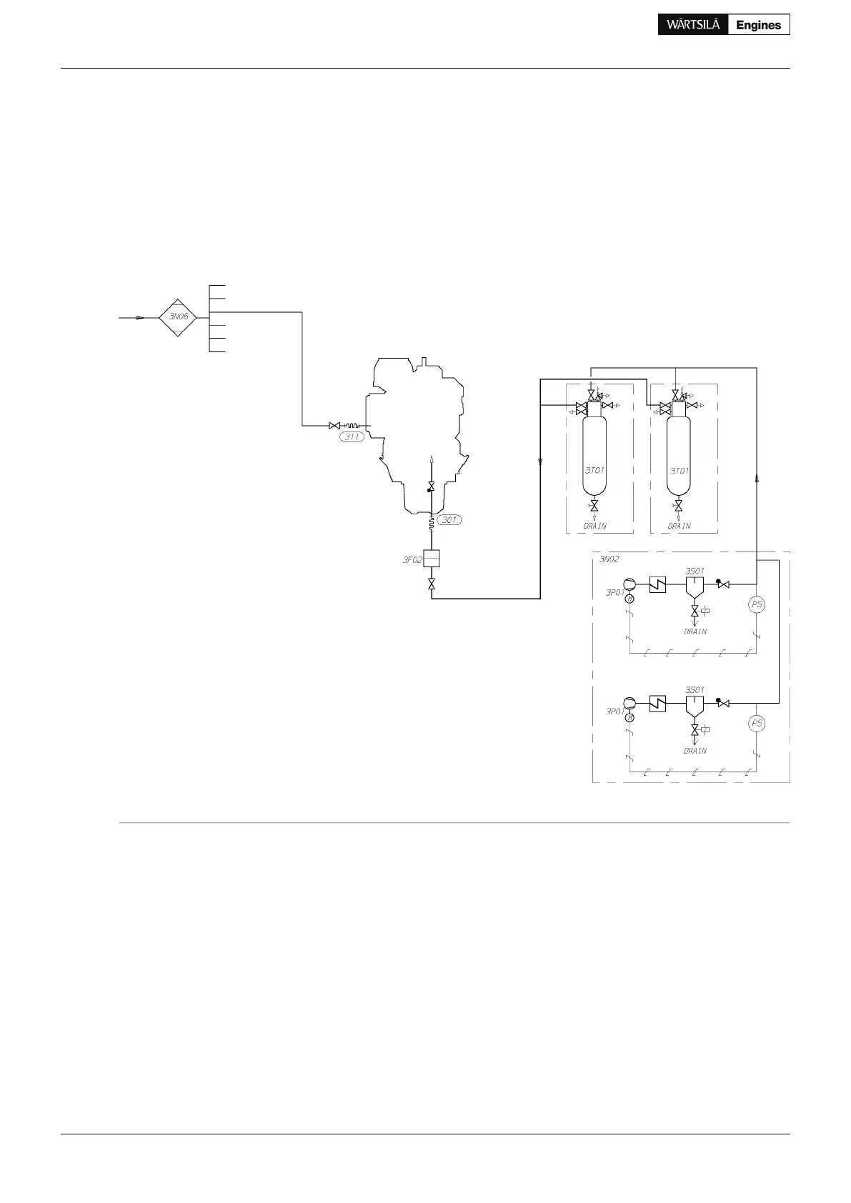
Figure 8.3 Example of external compressed air system (DAAE055759a)
Pipe connectionsSystem components
Starting air inlet, 3 MPa301Air filter (starting air inlet)3F02
Control air to bypass/wastegate valve311Starting air compressor unit3N02
Air dryer unit3N06
Compressor (Starting air compressor unit)3P01
Separator (Starting air compressor unit)3S01
Starting air vessel3T01
8.3.1 Star ting air compressor unit (3N02)
At least two starting air compressors must be installed. It is recommended that the compressors are capable
of filling the starting air vessel from minimum (1.8 MPa) to maximum pressure in 15...30 minutes. For exact
determination of the minimum capacity, the rules of the classification societies must be followed.
82 Product Guide Wärtsilä 34DF - 3/2012
Product Guide
8. Compressed Air System
 Loading...


