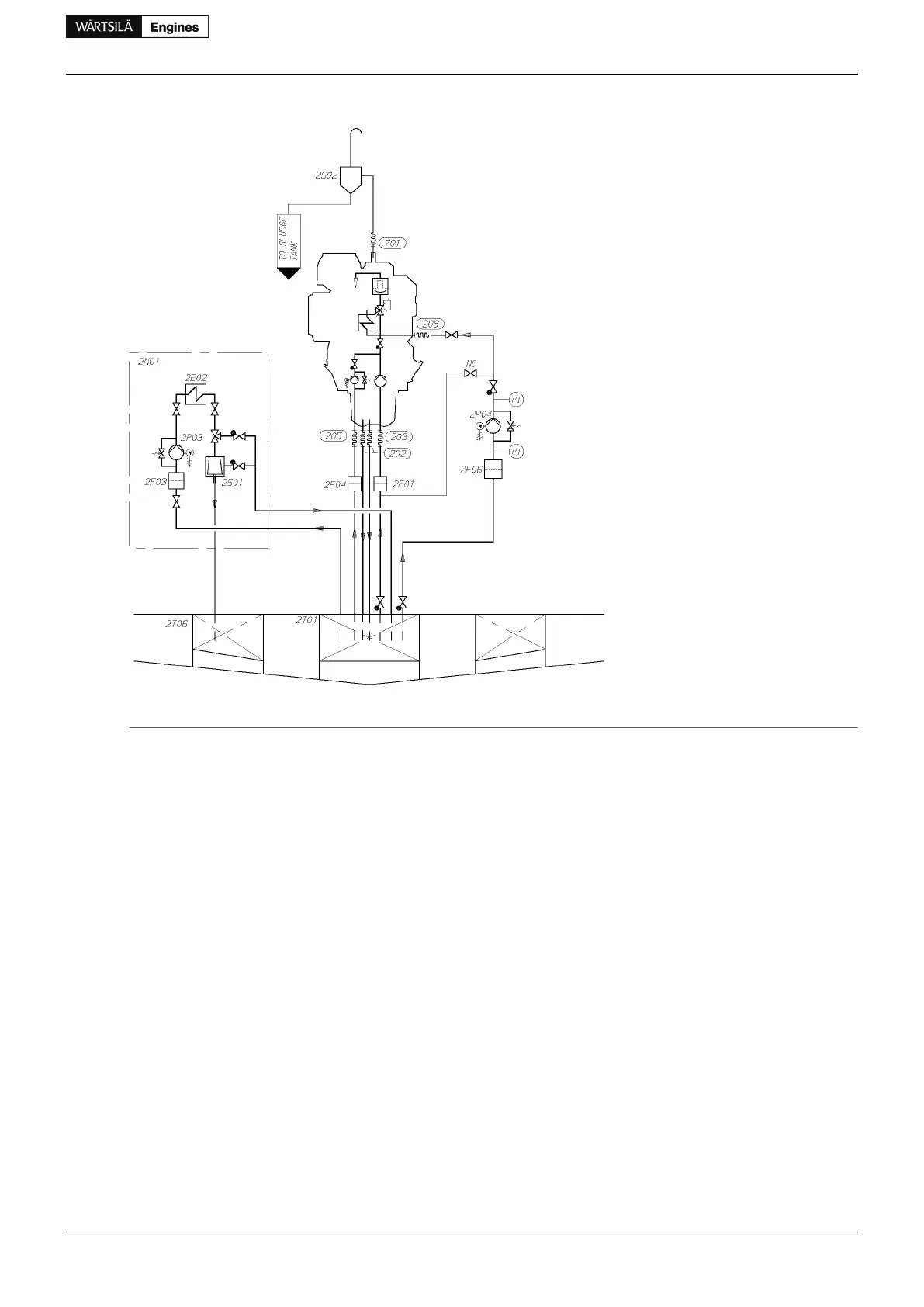
Figure 7.4 Example of lubricating oil system, dry oil sump (DAAE055758a)
Pipe connectionsSystem components
Lube oil outlet202Heater (separator unit)2E02
Lube oil to engine driven pump203Suction strainer (main lube oil pump)2F01
Lube oil to priming pump205Suction filter (separator unit)2F03
Lube oil from el.driven pump208Suction strainer (prelubricating oil pump)2F04
Crankcase air vent701Suction strainer (stand-by pump)2F06
Separator unit2N01
Separator pump (separator unit)2P03
Stand-by pump2P04
Separator2S01
Condensate trap2S02
System oil tank2T01
Sludge tank2T06
7.3.1 Separation system
Separator unit (2N01)
Each main engine must have a dedicated lubricating oil separator and the separators shall be dimensioned
for continuous separating. If the installation is designed to operate on gas/MDF only, then intermittent
separating might be sufficient.
Product Guide Wärtsilä 34DF - 3/2012 73
Product Guide
7. Lubricating Oil System
 Loading...


