EasyManua.ls Logo

Wascomat W630 Classic - User Manual

Wascomat W630 Classic
132 pages
Print Icon
To Next Page IconTo Next Page
Loading...
DOC. NO. 438.9205-85/07 EDITION 49.2004
W620, W630, W640,
W655, W675
Classic
SERVICE MANUAL
Question and Answer IconNeed help?

Do you have a question about the Wascomat W630 Classic and is the answer not in the manual?

Summary

Service Personnel Safety and Warnings

General Safety Precautions and Manual Usage

Warnings on installation, electrical hazards, personal injury, manual use, and warranty.

Machine Identification and Operational Guidelines

Machine Data Entry and Daily Operation Reminder

Section for machine details and reminder for daily operational procedures.

Machine Safety Signage Requirements

Mandatory Warning Signs Placement

Lists specific safety signs that must be affixed to the machine.

Critical Safety Instructions for Appliance Use

Appliance Usage, Installation, and Servicing Safety

Covers safe usage, installation, avoiding hazards, servicing, and child safety.

Owner, Operator, and Dealer Safety Notices

Daily Pre-Operation Checks and Maintenance

Daily checks for door interlock, signs, and general machine condition.

General Safety Precautions

Intended Use, Maintenance, and Repair Rules

Machine use, authorized maintenance, leak repair, and manual adherence.

Machine Performance and Connection Specifications

Performance Data and Connection Parameters

Inner drum volume, drum speed, heating types, weight, G-factor, and connection details.

Machine Dimensions and Component Layout (Metric)

Dimensional Specifications (mm) and Component Diagram

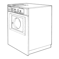
Table of dimensions in mm and diagram labeling key components.

Machine Dimensions and Component Layout (Imperial)

Dimensional Specifications (Inches) and Machine Views

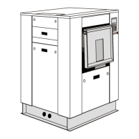
Table of dimensions in inches and diagrams showing machine views.

Dynamic Force and Floor Load Data

Frequency and Floor Load Specifications

Data on frequency of dynamic force and maximum floor load at extraction.

Machine Heating Alternative Specifications

E;W620 Heating Options

Voltage, kW, and Fuse A for No Heating/Steam and El Heating options.

E;W630 Heating Options

Voltage, kW, and Fuse A for No Heating/Steam and El Heating options.

E;W640 Heating Options

Voltage, kW, and Fuse A for No Heating/Steam and El Heating options.

E;W655 Heating Options

Voltage, kW, and Fuse A for No Heating/Steam and El Heating options.

E;W675 Heating Options

Voltage, kW, and Fuse A for No Heating/Steam and El Heating options.

Machine Description and Model Overview

Machine Models, Features, and Installation Environments

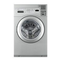
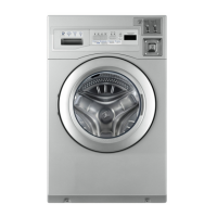
Lists models, describes features like programme unit, heating, and installation environments.

Machine Functional Overview

General Functions and Key Component Diagram

Introduction to machine functions and a diagram of key components.

Programme Unit and Control Panel Operation

Control Panel Interface and Programme Unit Logic

Describes control panel interface and how the programme unit controls machine functions.

Door Lock System Design and Operation

Door Lock Mechanism and Control Logic

Describes the door lock mechanism, safety features, and control logic.

Machine Systems Overview: Heating, Water, and Control

Heating, Water Connections, and Rear Control Unit

Details heating systems, water inlets, and the rear control unit components.

Detergent Dispensing and Drainage Systems

Detergent Compartment and Drain Valve Operation

Describes the detergent compartment layout and the drain valve's working principle.

Routine Maintenance Procedures

Daily and Periodic Maintenance Tasks

Lists daily checks and quarterly maintenance requiring qualified personnel.

Detailed Maintenance Checks and Safety

Internal Component Inspection and Heated System Checks

Inspects internal components, belts, heating elements, and prevents dry running.

Control Unit Component Breakdown

Front and Rear Control Unit Components

Lists components of the front and rear control units, including switches, contactors, and cards.

Control Unit Functional Roles

Programme Unit, Level Guards, and Thermostat Functions

Explains the functions of the programme unit, level guards, thermostat, and rotary switch.

Program Selector Card Jumper Settings (OG01)

Jumper Configurations for Program OG01

Details how jumpers A-I on the selector card modify wash program functions.

Program OL02 Jumper Settings

Jumper Configurations for Program OL02

Details jumper settings A-I for program OL02, covering valve activation and program timing.

Program OL03 Jumper Settings

Jumper Configurations for Program OL03

Details jumper settings A-F for program OL03, focusing on valve activation and program logic.

Front Control Unit Electrical Components

Main Power Switch and Heating Contactors

Describes the main power switch (Q1) and heating contactors (K21, K22).

Communication Card Functions and Connections

Fuses and Output Connection Blocks

Information on fuses F11/F12 and output blocks for external systems.

Optional Control Card Functionality

Option Card Availability for Program OL03

Notes that the option card is specific to machines with programme OL03.

Option Card Jumper Modifications

Modifying Rinse and Prewash Programs

Explains jumpers for warm rinses (N/M) and omitting prewash (O).

Option Card Jumpers for Water Level Control

Water Level Jumper Settings (R & S)

Describes jumpers R and S for selecting low/high water levels in wash phases.

Water Level Sensing System

Level Switch Operation and Faults

Explains the pressure-based level switch, its settings, and fault diagnosis.

Water Level Management and Troubleshooting

Water Level Check Procedure and High Level Issues

Steps to check water levels and troubleshoot high water level problems.

Thermostat System Details

Thermostat Specifications, Sensor, and Control Logic

Details thermostat specifications, sensor location, and temperature control logic.

Thermostat Replacement Procedures

Thermostat Tampering Warning and Replacement Steps

Warning about warranty voiding and steps for replacing the thermostat.

Door Lock System Components and Controller

Door Lock Mechanism, Switches, and Controller

Describes the door lock mechanism, micro switches, emergency arm, and controller.

Door Lock Mechanism: Locking Operation

Conditions and Activation for Door Locking

Details conditions required for locking and pulse activation.

Door Lock Mechanism: Unlocking Operation

Conditions and Activation for Door Unlocking

Details conditions required for unlocking and pulse activation.

Door Lock Error Code Diagnostics

LED Indicators for Normal and Error States

Describes LED behavior during normal operation and in various error states.

Door Lock Control System Interfaces

Reset Button, Voltage Supply, and Lock;Unlock Input

Covers reset button, voltage supply input (X90, X91), and lock/unlock request input (X92).

Door Lock Control Signal Inputs and Outputs

Rotation Sensor Input (X95) and Door Lock Output (X96)

Defines inputs from rotation sensor and output to door lock, including voltage requirements.

Emergency Door Lock Opening Procedure

Steps for Manual Door Lock Opening

Step-by-step guide to manually open the door lock in an emergency.

Door Lock Replacement Procedure

Steps for Replacing the Door Lock Assembly

Detailed instructions for removing and installing a new door lock.

Motor Safety Warnings

Safety Precautions for Capacitor and Filter Measurement

DANGER warning regarding safe measurement of capacitors and filters.

Motor System Description and Protection

Motor Installation, Control, and Overload Protection

Describes motor fitting, drive belt, contactor control, and thermal overload protection.

Motor Electrical Wiring Diagrams

Single-Phase and Three-Phase Motor Wiring

Wiring diagrams for single-phase and three-phase motors with speed selection.

Motor Overload Protection Details

Thermal Overload Protector Functionality and Reset

Details thermal overload protectors, their trip temperature, and manual reset capability.

Motor Replacement Procedures

Motor Disassembly and Assembly Steps

Step-by-step guides for disassembling to remove and then installing a new motor.

Motor Drive Belt Tension Adjustment

Drive Belt Tension Specifications and Adjustment Procedure

Table of tension specs and instructions for adjusting drive belt tension.

Drain Valve System Description and Operation

Drain Valve Components, Access, and Working Principle

Describes valve parts, access, and how water pressure operates it.

Drain Valve Repair and Disassembly

Safety Warning and Disassembly Steps for Drain Valve

Warning about water spillage and detailed steps for disassembling the drain valve.

Drain Valve Assembly and Testing

Steps for Assembling and Testing Drain Valve

Instructions for reassembling the drain valve, connecting hoses, and verifying operation.

Detergent Compartment Configuration and Operation

Detergent Compartment Layout, Connections, and Overflow

Describes the four compartments, water connections, and overflow protection.

Electric Heating System Details

Heating System Components and Element Specifications

Describes heating elements, sensor, contactors, and lists element sizes by model.

Heating System Functionality

Electric and Steam Heating Control Logic

Explains control logic for electric heating and steam valve operation.

Heating Element Replacement Procedure

Safety Warning and Replacement Steps for Heating Elements

Warning about water spillage and detailed steps for replacing heating elements.

Coin Meter Programming and Settings

Accessing Settings and Switch Functions (S1-S3)

Instructions for accessing settings and details on switches for ratio, price, and reduction.

Coin Meter Ratio Setting Configurations

Switch S1 Combinations and Ratio Setting Examples

Table of S1 combinations for ratios and examples of setting ratios.

Setting the Current Price on Coin Meter

Price Calculation Formula and Programming Examples

Formula (I = (P x A)/V) for price calculation and examples of programming scenarios.

Coin Meter Price Reduction Settings

Switch S3 for Price Reduction Settings

Details switch S3 combinations for setting price reductions (0-75%).

Pulley and Bearing Replacement Tool Kit

Complete Tool Kit Contents and Part Numbers

Lists part numbers and descriptions for the complete tool kit.

Pulley Removal Procedures

Preparing for Pulley Removal and Heat Application

Steps to remove C-clamp, affix puller, and use heat for easier removal.

Shaft Preparation and Adapter Mounting

Shaft Threading and Puller Adapter Installation

Instructions on threading the shaft end and mounting the puller adapter.

Pulley Mounting Process

Assembling Pulley Components and Test Run

Steps to assemble pulley components, secure, and perform a test run.

Bearing Kit Identification and Selection

Bearing Kits for Specific Models (Groups 1 & 2)

Lists part numbers for bearing kits for various machine models.

Bearing Removal Procedures

Removing Pulley, Wedge, and Measuring Shaft Distance

Instructions for removing pulley, wedge, and measuring shaft distance.

Bearing House Removal from Shaft

Loosening and Pressing Out Bearing House

Steps to loosen bolts and press out the bearing house.

Bearing and Seal Removal

Removing Front Bearing, Rear Gable, and Sealings

Steps to remove front bearing, rear gable, and sealings.

Bushing Removal from Shaft

Methods for Bushing Removal from Shaft

Describes methods like tapping or chiseling/grinding to remove the bushing.

Bearing House Cleaning and Preparation

Tapping Bearings Out and Cleaning Housing

Steps to tap bearings out and thoroughly clean the bearing house.

Bearing Installation Greasing Procedures

Greasing and Installing Front Bearing and Housing

Instructions for greasing and tapping the front bearing into the housing.

Rear Bearing and Sealing Ring Installation

Installing Rear Bearing and Sealing Rings

Steps to install the rear bearing and sealing rings into the housing.

Sealing Ring Installation Greasing

Greasing Bearing Housing for Sealings

Instructions to grease the bearing housing interior for easier sealing ring mounting.

First Sealing Installation Process

Greasing and Tapping First Sealing into Housing

Steps to fill first sealing with grease and tap it carefully into the housing.

Second Sealing Installation Process

Greasing and Installing Second Sealing and Spacer

Instructions for filling second sealing with grease, placing spacer, and pressing drift.

Third Sealing Installation Process

Mounting Third Sealing with Caution

Instructions to mount the third sealing, noting lip position and avoiding damage.

Bearing Housing Mounting and Shaft Preparation

Oil Lubrication Check, Shaft Threading, and Housing Mounting

Check oil system, thread shaft, and mount bearing housing to rear gable with correct orientation.

Rear Gable Assembly and Measurement Verification

Mounting Rear Gable Package and Verifying Measurements

Steps to mount rear gable package and check measurement between shaft end and bearing race.

Final Pulley Assembly Steps

Mounting Shaft Wedge, Pulley, and Gasket

Steps to mount shaft wedge, pulley components, and replace rear gable gasket.

Drum Package Installation and Final Checks

Inserting Drum Package and Performing Test Run

Steps to insert drum package and perform final test run.

Wascomat W630 Classic Specifications

General IconGeneral
BrandWascomat
ModelW630 Classic
CategoryWasher
LanguageEnglish

Related product manuals