Assembly and Parts, Cont.
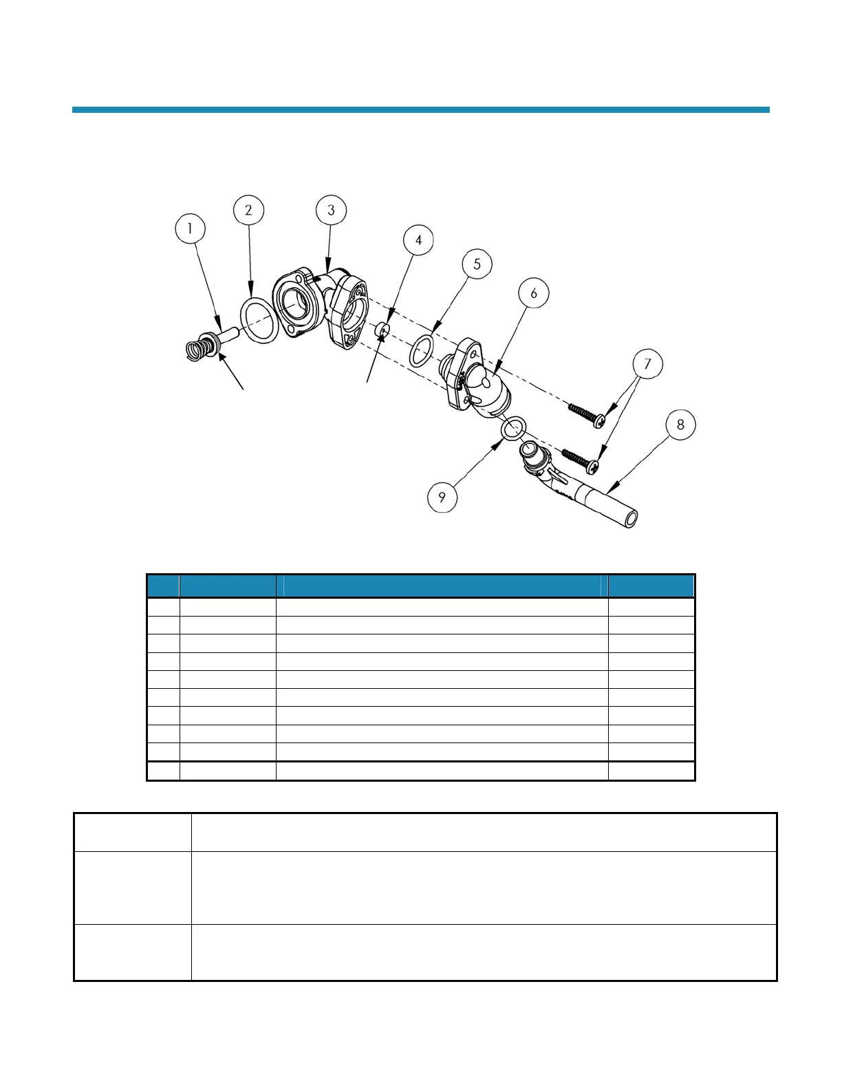
Brine Valve Housing Assembly
Concave side
Static O-Ring
Figure 19: Brine Valve Housing Assembly
Part # Description Quantity
1 53511 Piston Assembly (includes O-Ring & Spring) 1
2 90821 O-Ring 1
3 53510 Housing 1
4 90843 0.5 gpm Flow Control 1
5 93805 O-Ring 1
6 54314 Brine Valve Cap 1
7 90818 Screw, self-tapping 2
8 54315 Brine Valve Elbow 1
9 90828 O-Ring 1
54521 Entire Assembly (all of the above parts)
53511 Brine
Piston
The Piston should have an O-Ring on the shaft side of the flange and a spring pressed onto a boss on
the other side. The O-Ring should be free of defects such as cuts or debris on the shaft side.
53510 Housing
Just inside the entrance hole for the Brine Piston (53511) is a concave seat area that must be free of
defects such as nicks, indentations, or debris. This seat area ensures a leak-free seal for the static
O-Ring on the Brine Piston. If any defects are detected by visual inspection, repair or replace as
needed.
90843 0.5 gpm
Flow Control
The Flow Button has two distinct and different sides. One is “flat”; the other is “concave.” The button
should be centered in the housing opening with the four locator “ribs” with the concave side facing the
Housing End Cap (93247).
WaterBoss Softener Owner’s Manual 12/2/2010 28