6
REDUCED CLEARANCES
Under certain conditions the minimum clearances
may be reduced by means of:
(a) The use of listed pipe shields, installed in
accordance with the manufacturer’s instructions.
(b) Shields constructed in accordance with
NFPA211 (USA), Can3-B365 installation code
for solid fuel fired appliances.
(c) When listed pipe shields are used - top exit
option only - the clearances may be reduced to
9” from the pipe shield and 11” from stove back.
DOUBLE WALL CONNECTIONS
Double wall chimney connectors may be substituted
for the shielded pipe provided it is UL/ULC listed for
a 9” clearance or less.
WALL PROTECTORS
Materials and products listed for the purpose of
reducing clearance to combustibles shall be
installed in accordance with the conditions of the
listing and the clearances may be reduced by the
percentage reduction as stated in the wall shield
manufacturer’s instructions.
For clearance reduction systems using an air space
between the combustible wall and the wall protector,
adequate air circulation shall be provided by one of
the following methods.
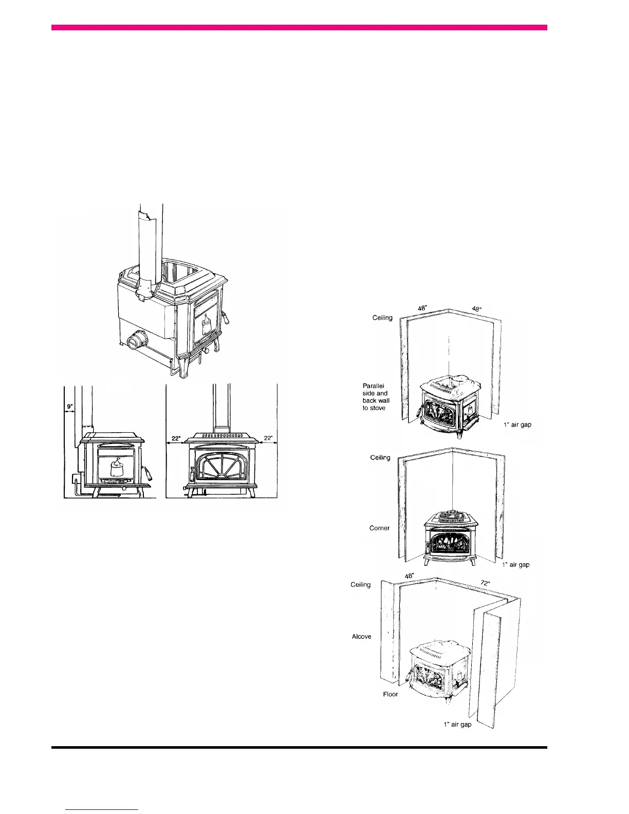
1. Adequate air circulation may be provided by
leaving all edges of the air protector open with at
least a 1” air gap.
2. If the wall protector is mounted on a single flat
wall, away from corners, an adequate air
circulation may be provided by leaving bottom
and top edges or only the side and top edges
open with at least a 1” air gap.
3. Wall protectors that cover two walls in a corner
shall be open at the bottom and top edges with
at least a 1” air gap.
4. All clearances shall be measured from the outer
surface of the combustible material to the
nearest point on the surface of the Waterford
Trinity MK II Stove disregarding any intervening
protection applied to the combustible material.
When using a manufactured wall shield system
observe local building codes and by-laws.
Fig.24
Fig.25
Fig.26
Fig.27
Fig.28
Fig.29
 Loading...