Starting Out
27
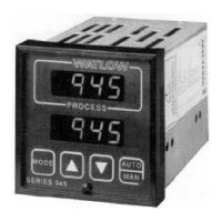
QPAC User's Manual
How to Operate QPAC, Chapter 3
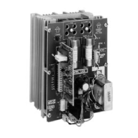
Fixed Bias
Connector
Gain
Pot
J3
TB-1
1
5
J1
08-5342
Motherboard Connector
Current Limit Pot
(AL Card only)
Bias
Pot
Gain
Pot
08-5411
TB-2
TB-1
4-20mA
5V
CT
1
2
1
5
Bias & Gain
Current Limit Adjustments
The AL Control Card is a phase angle control with the capability to limit the
maximum current to the load. A potentiometer on the AL adjusts the current
limit setting. See Figure 37. Use the following steps to adjust the current limit
on initial setup. The purpose of the procedure is to bring the power to the load
up slowly so that the maximum current to the load is not exceeded before the
current limit is adjusted.
Note: A short overcurrent through the load may occur, as the AL Card circuitry
detects the higher current, if the input signal from the temperature control is
abruptly increased.
1. Attach a clamp-on ammeter to the load line.
2. Adjust the AL card current limit potentiometer fully counterclockwise (for
minimum current flow).
3. Turn the temperature control ON and adjust the input signal to the control
card for zero percent power.
4. Turn the power to the QPAC ON.
5. Gradually increase the input signal.
6. Adjust the current limit potentiometer clockwise until current to the load is
measureable.
7. Gradually increase the input signal to 100% power, then adjust the current
limit potentiometer to obtain the desired maximum current to the load.
NOTE:
The AL Current
Limit must be
disabled (pot fully
clockwise - CW)
before bias and gain
can be adjusted.
Figure 37 -
AL (Rev. B)
Control Card
Figure 36 -
BV (Rev. B)
Control Card
BV Fixed Bias Connector
& Gain Adjustment
AL Bias, Gain, & Current Limit
Adjustments
 Loading...