Do you have a question about the Watlow 945 Series and is the answer not in the manual?
Details the process of installing and wiring the Series 945 control unit into a panel.
Step-by-step guide for physically installing the Series 945 control into its intended panel.
Covers the general principles and considerations for wiring the Series 945 control unit.
Explains the different types of sensor inputs and their corresponding wiring connections for the Series 945.
Details the wiring configurations for the primary output (Output 1) of the Series 945 controller.
Wiring diagram for the 0-5VDC process output for Output 1 on the Series 945.
Wiring diagram for Output 1 with a solid state relay without suppression.
Wiring diagram for Output 2 with a solid state relay with suppression.
Wiring diagram for Output 2 using a switched DC open collector output.
Wiring diagram for Output 2 using a 6 Amp mechanical relay.
Wiring diagram for Output 2 with a solid state relay without suppression.
Illustrates a typical system wiring configuration for the Series 945 controller.
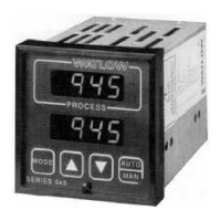
Details the function of each key and display element on the Series 945 control panel.
Instructions for setting the internal DIP switch for configuring the Series 945.
Procedure for accessing and navigating the setup menu of the Series 945 controller.
Explains the various setup parameters available for configuring the Series 945 controller.
Configures the type and behavior of Alarm 1 on the Series 945.
Configures the type and behavior of Alarm 2 on the Series 945.
Selects the level of operator lockout for the Series 945.
Determines the alarm type for Alarm 1 (process or deviation).
Determines the alarm type for Alarm 2 (process or deviation).
Details the various parameters used for operating the Series 945 controller.
Defines the band where controller proportioning is active for Output 1 or 2.
Describes the integral control action for eliminating offset or droop.
Explains the rate or derivative function for eliminating overshoot.
Represents the low process or deviation alarm for Alarm 1.
Represents the high process or deviation alarm for Alarm 1.
Represents the low process or deviation alarm for Alarm 2.
Represents the high process or deviation alarm for Alarm 2.
Adds or subtracts degrees from the input signal for calibration.
Initiates auto-tune for Output 1 for optimal control performance.
Explains the auto-tuning procedure for Output 1, heating only, to tune PID parameters.
Provides a guide for manually tuning the Series 945 PID parameters for optimal control.
Details how to switch between manual and automatic operation modes.
Instructions for setting alarm jumpers to configure alarm outputs.
Explains the two alarm types (Process/Deviation) and how to manage alarms.
Lists and describes error codes displayed by the Series 945 when faults occur.
Outlines the actions to take and conditions resulting from specific error codes.
Details methods and devices like snubbers and MOVs for noise reduction.
Explains how to identify and eliminate ground loops in the control system.
Procedure for accessing the calibration menu to configure parameters like dFL.
Step-by-step guide for calibrating thermocouple inputs on the Series 945.
Step-by-step guide for calibrating RTD inputs on the Series 945.
Procedure for calibrating the 0-5VDC input signal on the Series 945.
Procedure for calibrating the 4-20mA input signal on the Series 945.
Calibrating the 0-5V or 0-10V output signals of the Series 945.
Calibrating the 0-20mA or 4-20mA output signals of the Series 945.
Covers thermocouple and RTD input types, cold junction compensation, and selectable units.
| Operating Temperature | 0 to 55°C (32 to 131°F) |
|---|---|
| Mounting | Panel mount |
| Input Types | Thermocouple, RTD |
| Output Types | Relay, solid state relay (SSR) driver, DC linear voltage and current |
| Control Modes | ON/OFF, PID |
| Display | Dual 4-digit LED |
| Alarms | 2 programmable alarms |
| Enclosure Rating | NEMA 4X (IP65) front panel |
| Communication Options | RS-485 Modbus RTU |
| Dimensions | 96 x 96 mm (3.78 x 3.78 inches) |
| Product Series | 945 Series |
| Type | Temperature and process controller |