Page 2
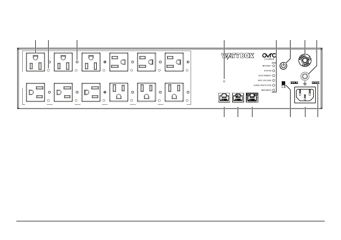
FRONT PANEL
A. Controllable outlets 1-12 – All outlets are switchable (IP controlled).
B. Power indicators 1-12 – Illuminate when power is on (one for each outlet).
C. Hook & loop lockdown screws 1-12 – Attaches to hook & loop fasteners for securing power adapters in place.
D. Reset button – Press and release to restart the network card, press and hold ve seconds to reset network settings, and press and
hold 10 seconds to restore to factory defaults.
E. Indicator LEDs – Show the status for Internet, System, Auto Reboot, Safe Voltage, Surge Protected, and Grounded. For more
information about indicator meanings, see page 10.
F. Power switch – Press to manually toggle the unit’s power outlets on or o. Outlets set for reset only are not aected.
G. Circuit breaker – 15A resettable breaker that trips when overamperage conditions occur.
CONTROLLED 1 CONTROLLED 2 CONTROLLED 3 CONTROLLED 4 CONTROLLED 5 CONTROLLED 6
NETWORK
RESET
120VAC 60Hz
POWER
SAFE
VOLTAGE
ACCUPS LINK
OFF
ON
WB-800-IPVM-12
CONTROLLED 7
FILTERED
CONTROLLED 8 CONTROLLED 9 CONTROLLED 10 CONTROLLED 11 CONTROLLED 12
A D E F G H
NMLKJI
B C
 Loading...