Installation Guidelines
Indoors
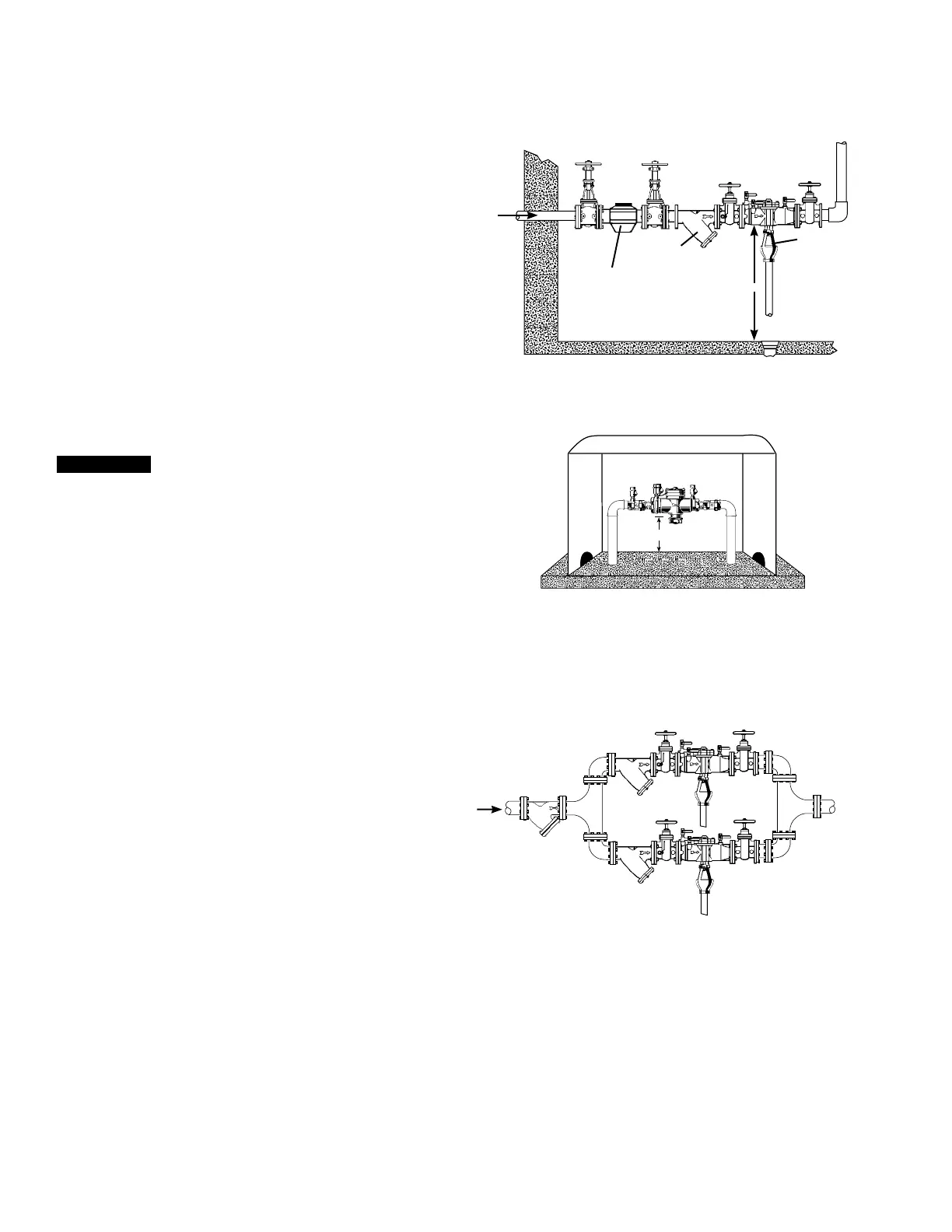
For indoor installations, the assembly needs to be easily
accessible to facilitate testing and servicing. If it is located in a
line close to a wall, be sure the test cocks are easily accessible.
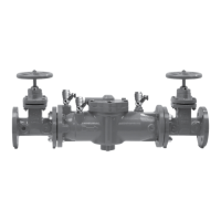
A drain line and air gap should be piped from the relief valve
connection as shown in Figure 1. This is where evidence
of discharge is clearly visible, signaling the need to protect
against water damage. Therefore, never install the assembly in
concealed locations. (For more information, download the ES-
AG/EL/TC specification at watts.com.)
Figure 1
Air Gap
Main
Strainer
Meter
2
1
⁄2" – 3"
12" Minimum
Outside
In an area where freezing conditions do not occur, the assembly
can be installed outside. The most satisfactory installation is
above ground; thus, the assembly should be installed in this
manner.
Backflow preventers should not be installed in pits unless
approved by local codes. In such cases, a modified pit
installation is preferred.
NOTICE
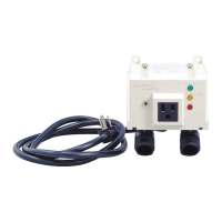
In an area where freezing conditions can occur, the assembly
should be installed above ground in an insulated enclosure, as
shown in Figure 2. (For more information, download the ES-WB
specification at watts.com.)
The assembly must be installed in an accessible location to
facilitate testing and servicing. A discharge line should be piped
from the air gap at the relief valve connection to ensure there is
adequate drainage. Never pipe the discharge line directly into a
drainage ditch, sewer, or sump. Never install the assembly where
any part of the unit could become submerged in standing water.
Figure 2
WattsBox
12" Minimum
Parallel
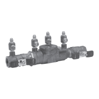
Two or more smaller-sized assemblies can be piped in parallel
(when approved) to serve a large supply pipe main, as shown in
Figure 3. This type of installation is employed where increased
capacity is needed beyond that provided by a single valve and
permits testing or servicing of an individual valve without shutting
down the complete line.
The number of assemblies used in parallel should be determined
by the engineer’s judgment based on the operating conditions of
a specific installation.
For parallel valve installations, the total capacity of the
assemblies should equal or exceed that required by the system.
2
1
⁄2" – 3"
*
Figure 3
2

 Loading...