3
Setting Up the Cellular Gateway
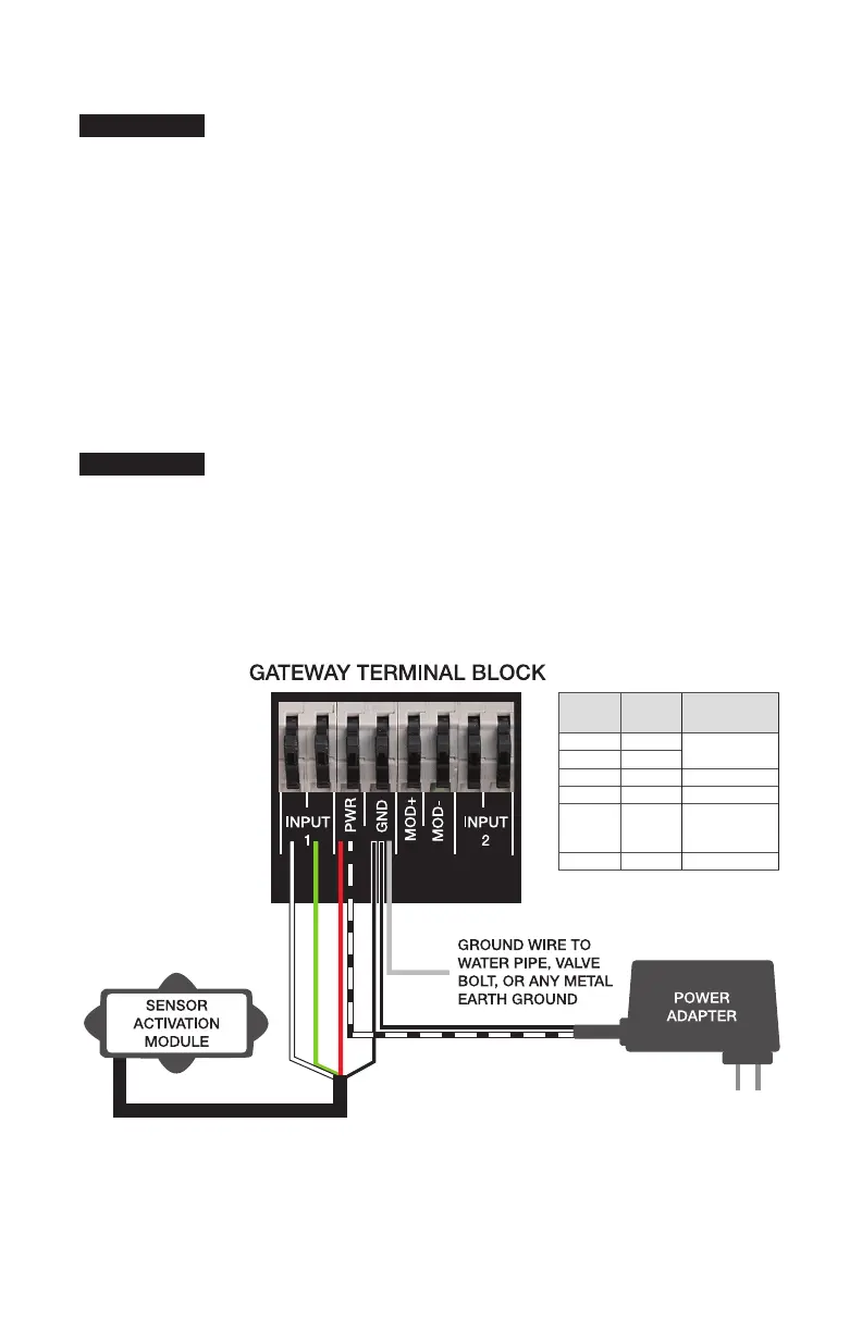
These instructions cover the connection of activation module
cable to the terminal block of the Cellular Gateway. The
4-conductor activation module cable should be attached to
the Cellular Gateway to transmit a normally open contact
signal and provide power to the activation module. The
contact signal closes when a discharge is detected.
When attaching the power adapter to the Cellular Gateway,
distinguish the positive wire from the negative one. The
positive wire has white stripes and must be inserted into the
power terminal; the negative wire, into the ground terminal.
Attach the activation module cable to the device before or
after it is mounted to a nearby wall or structure with the
mounting tabs and screws. Collect the Cellular Gateway and
mounting materials, power adapter, and Phillips screwdriver,
and wire stripper for this segment of the installation.
1. Remove the transparent cover from the device.
2. Use the wire stripper to cut away enough insulation to
expose 1 to 2 inches of the conductor wires and feed the
cable through the bottom port.
3. Insert the white wire (WH) and the green wire (GN) into
the first and second terminals of INPUT 1.
4. Feed the power adapter cord through the bottom port.
5. Connect the positive (black with white stripe) power adapter
wire (BK/WH) to the red wire (RD) of the activation module
cable and insert the wires into the PWR terminal.
6. Connect the negative (black with no stripe) power adapter
wire (BK) to both the black wire (BK) of the activation
module cable and the ground wire (SI) then insert the
wires into the GND terminal.
7. Skip MOD+ and MOD-. Reserved.
8. Reattach the device cover and plug the power adapter
into a 120VAC, 60Hz, GFI-protected electrical outlet.
If adding a second flood sensor to the configuration, insert
the white and green wires into the first and second terminals
of INPUT 2, the red wire into the PWR terminal, and the
black wire into the GND terminal.
When identifying a location to mount the Cellular Gateway,
choose an area away from large metal objects and struc-
tures that can block cellular signal. The cellular antenna is
placed inside the housing on the upper right side. Ensure
that the antenna side is clear of walls, wires, pipes, or
other obstructions.
NOTICE
The earth ground must be connected to the Cellular
Gateway before the flood sensor is put in operation.
NOTICE
BK/WH
WH
GN
RD
BK
SI
BK
LETTER
CODE
WIRE
COLOR FUNCTION
WH White Normally open dry
contact input
GN Green
RD Red Positive voltage
BK Black Circuit ground
BK/WH Black
with white
stripe
Positive voltage
SI Silver Earth ground

 Loading...