Optional
Xylan
Coating
17A
6
1
2
3
4
5
7
8
9
11
12
13
14
15
16
17
18
10
10 IOM-ACV-115-4_6115-4 2115 EDP# 1917035 © 2021 Watts
IOM-ACV-115-4_6115-4 2115 EDP# 1917035 © 2021 Watts 11
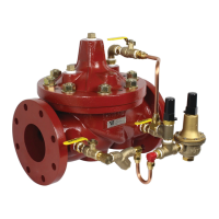
ACV Assembly Diagram – Series LFM115-4
Item Description Material
1 Pipe Plug Lead Free Brass
2 Cover ASTM A536 65-45-12 Epoxy Coated Ductile Iron
3 Cover Bearing ASTM A276 304 Stainless Steel
4 Stud with Cover Nut and Washer ASTM A570 Gr.33 Zinc Plated Steel
5 Body ASTM A536 65-45-12 Epoxy Coated Ductile Iron
6 Spring ASTM A276 302 Stainless Steel
7 Stem Nut ASTM A276 304 Stainless Steel
8 Lock Washer ASTM A276 304 Stainless Steel
9 Stem Washer ASTM A276 304 Stainless Steel
10 Diaphragm Washer ASTM A536 65-45-12 Epoxy Coated Ductile Iron
11 Diaphragm* Buna-N (Nitrile)
12 Disc Retainer ASTM A536 65-45-12 Epoxy Coated Ductile Iron
13 Seat Disc* Buna-N (Nitrile)
14 Spacer Washer* x5 NY300 Fiber*
15 Disc Guide ASTM A743 CF8M (316) Stainless Steel
16 Shaft ASTM A276 304 Stainless Steel
17 Seat Ring** ASTM A743 CF8M (316) Stainless Steel
17A Seat Screw** (8" and Larger) ASTM A276 304 Stainless Steel
18 Seat Gasket* Buna-N (Nitrile)
* Contained in Main Valve Repair Kit
**Note: 6 inch and Smaller Valves, Seat Ring is threaded
Installation: If unit is installed in any orientation other than
horizontal (cover up) OR extreme space constraints exist,
consult customer service prior to or at the time of order.
NOTICE