WM_PRJ_Q2400_PTS_005 -007
18th January 2006
Confidential©
All rights reserved
Page: 17 / 51
This document is the sole and exclusive property of WAVECOM. Not to be
distributed or divulged without prior written agreement.
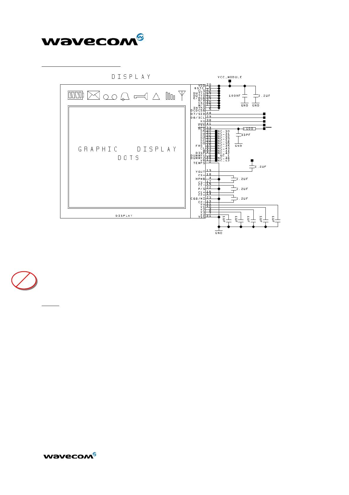
Typical implementation:
VCC
VCC
SPI_IO
SPI_CLK
GPO or GPIO
SPI_EN
RST
Figure 4: Example of SPI Bus typical implementation
2.2.2.2 Two-wire interface
The two-wire interface includes a CLK signal (SCL) and a DATA signal (SDA)
complying with a standard 96 kHz interface. The maximum speed transfer is
400 kbits/s.
Note:
The two-wire interface is reserved for future use. A software emulated
version of this interface using GPIOs is available. See “AT Command Interface
Guide” [3] for more information.
2.2.3 SPI Auxiliary bus
A second SPI Chip Enable (called SPI_AUX) can be used to add a SPI peripheral
to the WISMO Quik Q24x6 sub-series.
2.2.4 Keyboard interface
This interface provides 10 connections:
• 5 rows (ROW0 to ROW4),
• 5 columns (COL0 to COL4).
The scanning is a digital one, and the debouncing is done in the WISMO
module. No discrete components like R, C (Resistor, Capacitor) are needed.
T
T
T
 Loading...