WM_PRJ_Q2400_PTS_005 -007
18th January 2006
Confidential©
All rights reserved
Page: 30 / 51
This document is the sole and exclusive property of WAVECOM. Not to be
distributed or divulged without prior written agreement.
Recommended characteristics for the speaker:
• Type: 10 mW, electro-magnetic.
• Impedance: 32 to 150 Ω.
• Sensitivity: 110 dB SPL min. (0 dB = 20 µPa).
• Frequency response compatible with the GSM specifications.
For possible references, see chapter § 9.4.
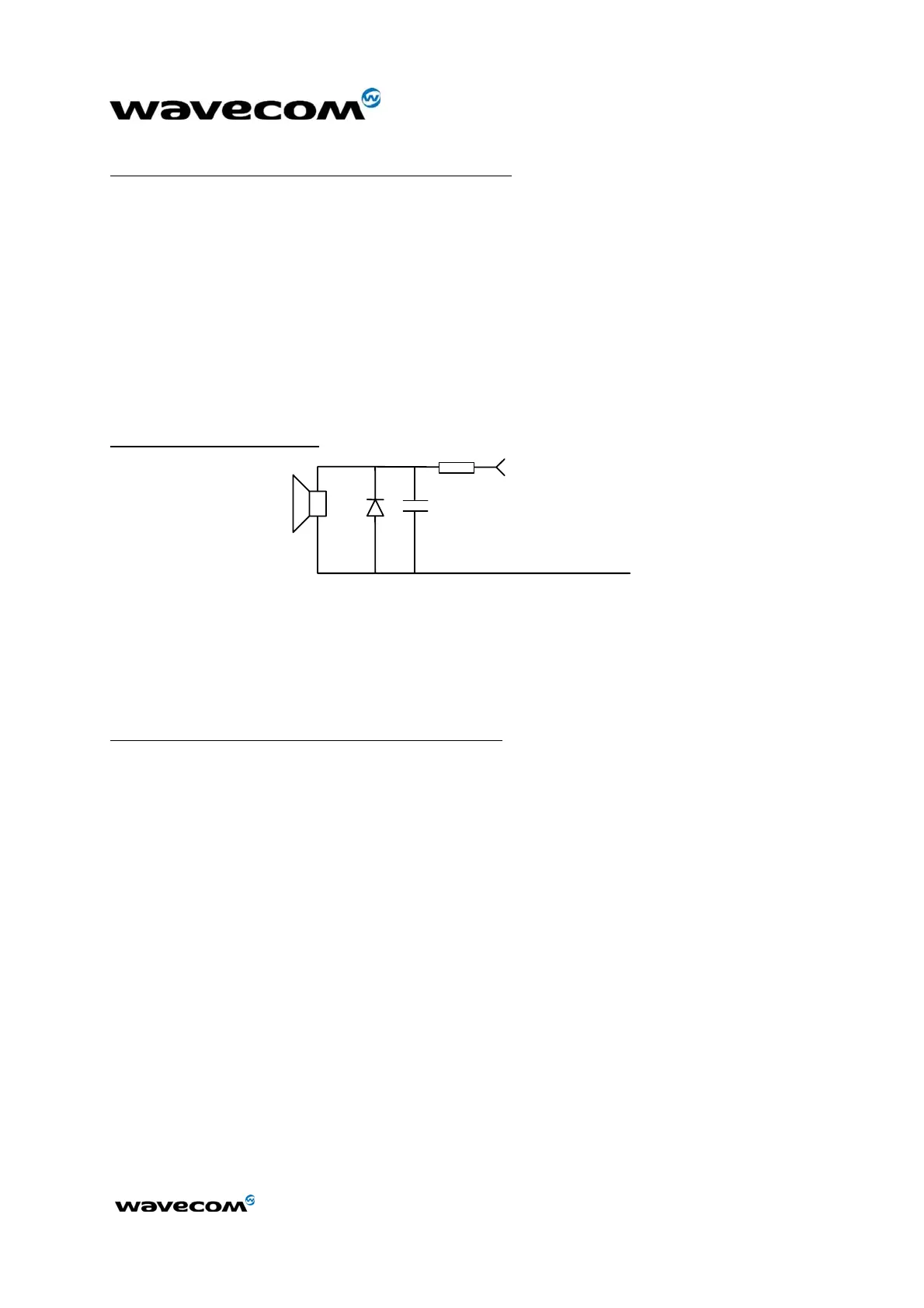
2.3.2.3 Buzzer Output
The buzzer output (BUZ) is a digital one. A buzzer can be directly connected
between this output and VBATT. The maximum current is 80 mA (PEAK).
A diode against transient peak voltage must be connected as described below.
Typical implementation:
C1
D1
VBATT
BUZ
R1
Figure 18: Example of Buzzer implementation
R1 must be chosen in order to limit the current at I
PEAK
max (recommended
values 10 Ω to 50 Ω).
C1 = 0 to 100 nF (depending on the buzzer type).
Recommended characteristics for the buzzer:
• Type: electro-magnetic.
• Impedance: 7 to 30 Ω.
• Sensitivity: 90 dB SPL min @ 10 cm.
2.3.2.4 Routing constraints
To get better acoustic performances, basic recommendations are the following:
• The SPKxx lines must be routed in parallel, without any wire in between.
• The MICxx lines must be routed in parallel, without any wire in between.
• All the filtering components (RLC) must be placed as close as possible to
the associated MICxx and SPKxx pins.
 Loading...