5.1
FACTORY
REPAIR
Wavetek
maintains
a factory repair
department
for
those
customers
not
possessing
the
necessary personnel
or
test
equipment
to
maintain
the
instrument.
If an
instrument
is
returned
to
the
factory
for
calibration
or
repair, a
detailed
description
of
the
specific
problem
should
be
attached
to
minimize
turnaround
time.
5.2
REQUIRED
TEST
EQUIPMENT
DVM (3%
digit)
Distortion
Analyzer
(
1%
F.S.)
HP334A
Oscilloscope
(~
40
MHz
bandwidth,
X
10 horizontal
magni-
fication,
de
triggering
to
1 Hz)
BNC
Termination
(500
~
1%,
~
1W)
Frequency
Counter
(6 digits, time base
accuracy~
50
ppm)
Low
Frequency
Spectrum
Analyzer
HP3580A
5.3
REMOVING
GENERATOR
COVER
For
main
board
access, remove
the
four
screws in
the
lower
cover, place
the
instrument
on
its
feet
and
lift
off
the
top
cover.
For
later access
to
the
synthesizer
board,
remove
the
four
screws from
the
inside corners
of
the
lower
board
that
attach
it
via
standoffs
to
the
lower cover.
Do
not
remove
the
lower
cover
unless necessary, because
it
supports
front
and
rear
panels.
SECTION
5
CALIBRATION
5.4
CALIBRATION
After
referring
to
the
following preliminary
data,
perform
calibration,
as necessary,
per
table
5-1.
If
performing
partial
calibration,
check
previous settings
and
adjustments
for
applicability.
1.
Unless
otherwise
noted,
all
measurements
made
at
the
500
OUT
connector
should
be
terminated
into
a
50U
(~
1%,
1W)
load.
2. Before
connecting
the
unit
to
an ac source,
check
the
ac
line
circuit
to
make sure
the
115/230
volt
switch
is
set
at
the
correct
position (see paragraph
2.2).
3.
Start
the
calibration by setting
the
front
panel
switches
as follows:
Dial
..................................
2.0
FREOMULT
.........................
X
1K
Mode (toggle switch) . . . . . . . . . . . . . . .
Toward
Dial
Digital
Switch
. . . . . . . . . . . . . . . . . . . . . . . .
0.1000
DC
OFFSET
...........................
OFF
Function
..............................
DC
AMPLITUDE
.
. . . . . . . . . . . . . . . . . . . . . . . . . ccw
ATTENUATION
..........................
0
4.
Allow
the unit to warm
up
at least
30
minutes for
final calibration.
Start
the calibration on main
board. All test points are located
on
the main
board.
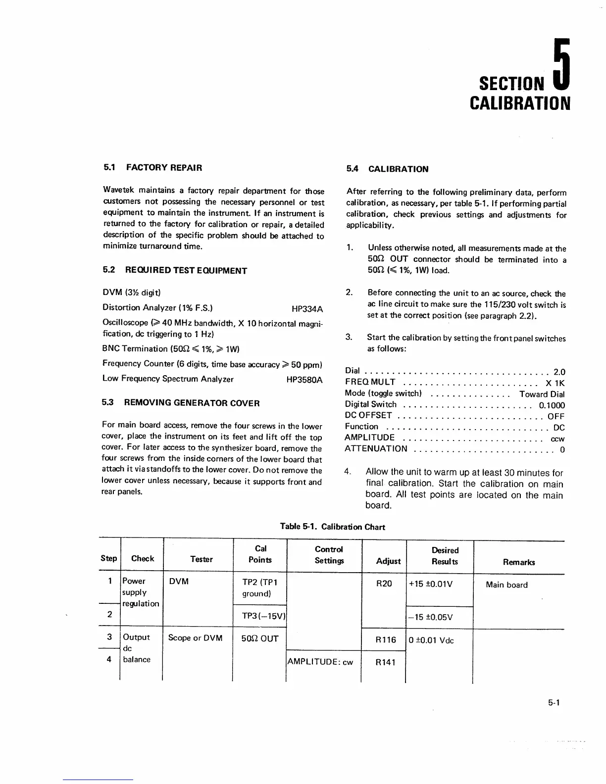
Table 5-1. Calibration
Chart
Cal
Control
Desired
Step
Check
Tester
Points
Settings
Adjust
Results Remarks
1
Power
DVM
TP2(TP1
R20
+15
±0.01V
Main
board
supply
ground)
-
regulation
2
TP3(-15V)
-15
±0.05V
3
Output
Scope
or
DVM
500
OUT
R116
0
±0.01
Vdc
-
de
4
balance
AMPLITUDE:
cw
R141
5-1
 Loading...