CHAPTER 9 CLICK 110 87
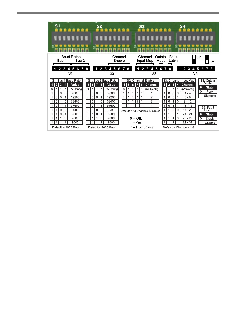
Figure 9.6 – Click 110 DIP Switches
e Click 110 features three DIP switches labeled S1, S2 and S3 on the label and in the pic-
ture above. (e fourth switch, labeled S4, is currently not used.) Each DIP switch is used to
congure one or two dierent settings, for a total of six dierent congurable parameters:
Bus 1 baud rate
Bus 2 baud rate
Channel enable
Channel input map
Outstation mode
Fault latch
Each parameter (except fault latch and outstation mode) has a way to pick between Hard-
ware/Soware modes. If Soware mode is selected, the parameter must be congured using
the front panel menu or Click Supervisor. If Hardware mode is selected, the parameter can
be congured using the switches. In this case, the setting can be viewed but not changed via
Click Supervisor and the front panel menu.
Baud Rate
e baud rates for the two RS-485 buses, bus 1 and bus 2 (see the faceplate of the device for
which RJ-11 jacks are for each bus), may be independently congured using the switches
on the rst DIP switch, labeled S1.