344940 REV2 03/17/2020
©
Copyright 2020 Wayne Dalton, a division of Overhead Door Corporation 16
STEP 8
APPLYING COUNTERBALANCE SPRING TENSION (MANUAL LIFT-UP, CRANK, AND GCX MOTOR OPERATION ONLY).
The amount of initial revolutions (IR’s) as indicated on the installation drawing and on the barrel “rev tag” is the THEORETICAL STARTING POINT for the required spring tension.
In most cases this gure is correct, but due to variations in steel, springs, friction, etc., slight adjustments may be required.
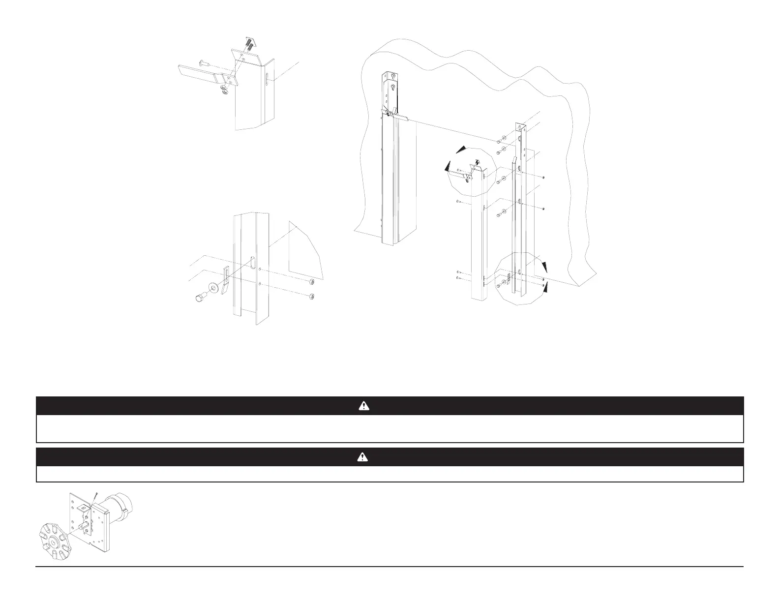
Install the adjusting wheel and cotter pin as shown. Using approved winding bar, rotate the adjusting wheel (AW) slightly in both directions to de-
termine the neutral point of the tension shaft. Insert the two winding bars securely into the holes in the AW as shown on page 18.
CAUTION
ALWAYS WIND COUNTERBALANCE SPRING TENSION WHEN THE SHUTTER IS IN THE UP POSITION. THE SPRINGS ARE UNDER THE LEAST AMOUNT OF TENSION AT THIS
POINT.
WARNING
VERIFY THAT AT THIS POINT, THE ADJUSTING WHEEL IS FREE AND THERE IS NO SPRING TENSION.
A
INNER GUIDE ASSEMBLY
B
DETAIL A
DETAIL B