SECTION I
INSTALLATION
A. GENERAL
The
Wayne HSG200 and HSG400
power
gas
conversion burners are adaptable
to
most
types of
central heating
plants previously
fired by
power
oil
burners. Typical heating
plants
are
gravity
and forced
air circulation furnaces, hot water,
steam
or vapor
boilers.
Power
burner design makes the
HSG200
and
HSG400 well
suited
for "negative draft" fired
appliances where an oil burner
is
being replaced.
lnstallation of these
power
gas
conversion burner
models must conform to local
codes, or
in their
absence, the
American National
Standard
for the
Installation
of
Domestic
Gas Conversion
Burners.
ANS|Z21.8
-
and the National Flue
Gas Code,
ANSlZ223.1
or
current
standard
year.
NOTICE: ANSI
or
local installation
code compliance
is
the
sole
responsibility of the
qualified
installer.
VENTILATION
The HSG conversion burner models covered by this
manual shall
not
be
installed
in an appliance located
where
normal
air circulation or infiltration is
limited in
providing
all the air necessary for
proper
combustion
and draft hood dilution air.
ln
ooen
basements of homes of normal construction
(without
basement storm
windows
or tight stair doors)
infiltration
of combustion air
is
usually sufficient
to
replace that drawn up the
flue,
so special
provisions
are
seldom
necessary.
When
the
heating
appliance
is installed in
a
tightly
closed
room without
ventilation
openings to outdoors, or other
rooms,
provisions
shall
be made for
supplying air
for
combustion through special
openings,
one
near the floor
line
and the other
near
the ceiling. Each is to be
sized
on the basis of one square
inch
(645.2mm')
or more of
free
area each
1,000 BTU
(.29kW)
input
per
hour.
When
the building
is
of unusually tight construction,
has
kitchen and/or bathroom
ventilation
fans which may be
used for
exhausting air
to
outdoors, or
has
a
vented
fireplace, it is recommended that combustion air be
supplied
to the furnace room through intakes extending
to
the
outside
of
the
building and terminating
in
down
turned
fittings,
suitably arranged to
prevent
obstruction
from
snow
or
rain,
and including a
protecting
screen
not
smaller than
1/4 inch
(6.35mm)
mesh.
HEATING APPLIANCE INSPECTION
Clean
the
appliance
heat
exchanger
interior,
combustion
chamber and
flue
connections.
Remove
all
adhering tars, scale, dirt and
soot.
lnspect the heat
exchanger
for
obvious and
potential
flue
gas
leaks.
Cement all
joints
around the
appliance base
and
access openings to
prevent
air
and/or
flue
gas
leakage
into
or out of the combustion chamber.
Warm Air Furnaces*
-
Make
certain the electrical
characteristics of the
fan
and
limit
switch correspond to
those
required
by this burner and that
they are
in
proper
working
order.
Hot
Water
Boilers*
-
Make
certain water temperature
and altitude
gauges,
pressure
relief
valves are in
proper
working
order.
Steam
Boilers*
-
Make certain the system is
pressure
tight, and that the
pressure gage
and
pop
off
safety
valve
are in
proper
working
order.
Existing water
sight
glass
permits
clear observation of boiler water level.
*Where
applicable,
existing temperature
of
pressure
limit
switch or
low water cut-off
switch
operation and
electrical characteristics
shall
be checked to determine
their compatibility to the
gas
control circuitry of this
burner.
D.
CHIMNEY,
FLUE PIPE AND DRAFT CONTROL
The chimney should be
inspected
for unsafe
conditions such as excessive soot accumulation,
deteriorated
masonry,
blockage or
potential
blockage.
NOTICE: No manually adjustable flue
pipe
damper is
permitted
on any
gas
burner
installation.
The chimney
should
be lined
with
a corrosion resistant
material,
lf the chimney
is
unlined, consult
your
local
gas
utility for recommendations.
WARNING:
Under
no circumstances
should
the flue
pipe
be connected to
the
chimney of an open
fireplace.
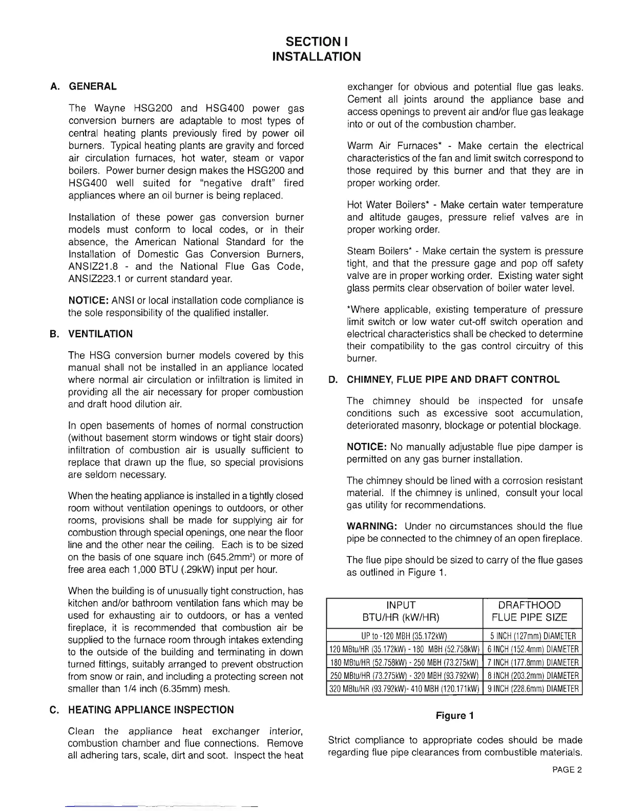
The flue
pipe
should
be
sized
to carry of the flue
gases
as
outlined in Figure 1.
Figure 1
Strict compliance
to
appropriate
codes
should
be made
regarding flue
pipe
clearances
from
combustible
materials,
B.
INPUT
BTU/HR
(kW/HR)
DRAFTHOOD
FLUE PIPE
SIZE
UP to -120 MBH
(35.172kW)
5 INCH
(127mm)
DIAMETER
120 MBtu/HR 135172kM
-
180 MBH
(52.758kW)
6 INCH
(152.4mm)
DIAMETER
180
MBtu/HR
(52.758kM
-
250
MBH
(73.275kW)
7 INCH
{177.8mm)
DIAMETER
250 MBtu/HR f3.275k$ - 320 MBH {93.792kW)8 INCH
(203.2mm)
DIAMETER
320 MBtu/HR
(93
792kW)- 410 MBH
(120.171kW)
I INCH
(228.6mm)
DIAMETER
c.
PAGE 2
SECTION I
INSTALLATION
A.
GENERAL
The Wayne HSG200 and HSG400 power gas
conversion burners are adaptable to most types of
central heating plants previously fired by power oil
burners. Typical heating plants are gravity and forced
air circulation furnaces, hot water, steam or vapor
boilers. Power burner design makes the HSG200 and
HSG400 well suited for "negative draft" fired
appliances where
an
oil burner
is
being replaced.
Installation of these power gas conversion burner
models must conform to local codes, or
in
their
absence, the American National Standard for the
Installation of Domestic Gas Conversion Burners,
ANSIZ21.8 - and the National Flue Gas Code,
ANSIZ223.1 or current standard year.
NOTICE:
A1'JSI
or local installation code compliance
is
the sole responsibility of the qualified installer.
B.
VENTILATION
The
HSG
conversion burner models covered
by
this
manual shall not
be
installed
in
an
appliance located
where normal air circulation or infiltration
is
limited
in
providing
all
the air necessary for proper combustion
and draft hood dilution
air.
In
open basements of homes of normal construction
(without basement storm windows or tight stair doors)
infiltration of combustion air
is
usually sufficient to
replace that drawn
up
the flue,
so
special provisions
are seldom necessary.
When the heating appliance
is
installed
in
a tightly closed
room
without ventilation openings to outdoors, or other
rooms,
provisions shall
be
made
for
supplying air for
combustion through special openings,
one
near
the
floor
line and the other near
the
ceiling.
Each
is
to
be
sized
on
the
basis of
one
square
inch
(645.2mm
2
)
or more of
free
area each 1,000
BTU
(.29kW) input per
hour.
When
the
building
is
of unusually tight construction, has
kitchen and/or bathroom ventilation fans which may
be
used for exhausting air to outdoors, or has a vented
fireplace,
it
is
recommended that combustion air
be
supplied to the furnace room through intakes extending
to
the outside of
the
building
and
terminating
in
down
turned fittings, suitably arranged to prevent obstruction
from snow or
rain,
and
including a protecting screen not
smaller than 1/4 inch (6.35mm) mesh.
C.
HEATING APPLIANCE INSPECTION
Clean the appliance heat exchanger interior,
combustion chamber and flue connections. Remove
all
adhering tars, scale, dirt and soot. Inspect the heat
exchanger for obvious and potential flue gas leaks.
Cement all joints around the appliance base and
access openings
to
prevent air and/or flue gas leakage
into or out of the combustion chamber.
Warm Air Furnaces* - Make certain the electrical
characteristics of the fan and limit switch correspond to
those required
by
this burner and that they are
in
proper working order.
Hot Water Boilers* - Make certain water temperature
and altitude gauges, pressure relief valves are
in
proper working order.
Steam Boilers* - Make certain the system
is
pressure
tight, and that the pressure gage and pop off safety
valve are
in
proper working order. Existing water sight
glass permits clear observation of boiler water level.
*Where applicable, existing temperature of pressure
limit switch or low water cut-off switch operation and
electrical characteristics shall
be
checked to determine
their compatibility to the gas control circuitry of this
burner.
D.
CHIMNEY, FLUE PIPE AND DRAFT CONTROL
The chimney should be inspected for unsafe
conditions such as excessive soot accumulation,
deteriorated masonry, blockage or potential blockage.
NOTICE:
No
manually adjustable flue pipe damper is
permitted
on
any gas burner installation.
The chimney should
be
lined with a corrosion resistant
material.
If
the chimney
is
unlined, consult your local
gas utility for recommendations.
WARNING: Under
no
circumstances should the flue
pipe
be
connected to the chimney of
an
open fireplace.
The flue pipe should
be
sized
to
carry of the flue gases
as
outlined
in
Figure
1.
INPUT DRAFTHOOD
BTU/HR (kW/HR) FLUE PIPE SIZE
UP
to
-120
MBH
(35.172kW)
51NCH
(127mm)
DIAMETER
120
MBtu/HR
(35172kW)
-180
MBH
(52.758kW)
6
INCH
(152.4mm)
DIAMETER
180
MBtu/HR
(52.758kW)
-
250
MBH
(73.275kW)
7
INCH
(177.8mm)
DIAMETER
250
MBtu/HR
(73.275kW)
-
320
MBH
(93.792kW)
8
INCH
(203.2mm)
DIAMETER
320
MBlu/HR
(93.792kW)-
410
MBH
(120171
kW)
9
INCH
(228.6mm)
DIAMETER
Figure 1
Strict compliance to appropriate codes should
be
made
regarding flue pipe clearances from combustible materials.
PAGE 2
 Loading...


