EasyManua.ls Logo

Wayne HSG400 User Manual

Wayne HSG400
52 pages
To Next Page IconTo Next Page
Page #1 background imageLoading...
Page #1 background image
WAYNE COMBUSTION SYSTEMS
801 GLASGOW AVE.
FORT WAYNE, IN 46803
PHONE: (260) 425-9200
(855) WAYNECS
(800) 443-4625
FAX: (260) 424-0904
www.waynecombustion.com
Manual 62484 | Revision D | Publication Date: 4/25/2018
Note: Dimensions in parentheses ( ) are informational only. English values take priority.
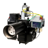
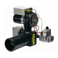
HSG200
HSG400
SPECIFICATIONS
BURNER MODELS MINIMUM INPUT MAXIMUM INPUT Air Tube Standard Lengths
HSG200 60,000 Btu/hr (18 kW) 200,000 Btu/hr (59 kW) 6, 9,12 in. (153, 229, 305 mm)
HSG400 200,000 Btu/hr (59 kW) 400,000 Btu/hr (117 kW) 6, 9,12 in. (159, 229, 305 mm)
FUELS: Natural Gas and LP Gas FLAME SAFETY: 24 Vac Electronic IGNITION: 7300 Vac Direct Spark
AVAILABLE VOLTAGES: 120 Vac 60 Hz, 230 Vac 50/60 Hz 1 Phase
AIR TUBE DIAMETER: 4 in (101.6 mm) MOUNTING: Adjustable Flange is standard; Pedestal Mount is Optional
Gas Burners
CSA CERTIFICATION:
189810-1154925
ANSI Z21.17
MASS G3-0903-67
READ THIS MANUAL BEFORE USING THIS PRODUCT. FAILURE TO FOLLOW THE
INSTRUCTIONS AND SAFETY PRECAUTIONS IN THIS MANUAL CAN RESULT IN
SERIOUS INJURY OR DEATH. KEEP THIS MANUAL FOR FUTURE REFERENCE.
INSTALLTION OF THE BURNER MUST BE DONE BY A QUALIFIED INSTALLER IN
ACCORDANCE WITH REGULATIONS OF THE NATIONAL FUEL GAS CODE ANSI
Z223.1/NFPA54, AND IN COMPLETE ACCORDANCE WITH ALL LOCAL CODES AND
AUTHORITIES HAVING JURISDICTION.
A QUALIFIED INSTALLER IS THE PERSON WHO IS RESPONSIBLE FOR THE
INSTALLATION AND ADJUSTMENT OF THE EQUIPMENT AND WHO IS LICENSED
TO INSTALL GAS-BURNING EQUIPMENT IN ACCORDANCE WITH ALL CODES AND
ORDINANCES.
Other manuals for Wayne HSG400

Questions and Answers:

Wayne HSG400 Specifications

General IconGeneral
BrandWayne
ModelHSG400
CategoryIndoor Fireplace
LanguageEnglish

Summary

SPECIFICATIONS

Overview of Safety Warning System and Your Responsibilities

Hazard Definitions

Defines various hazard levels (DANGER, WARNING, CAUTION, NOTICE) and their implications for safety.

SECTION I: INSTALLATION AND SETUP

VISUAL INSPECTION OF THE HEATING SYSTEM

Inspects the heating appliance for suitability and air circulation for proper burner operation.

INSPECTION OF FLUE PIPE AND CHIMNEY

Ensures proper venting of combustion gases, checking for clearances and condition.

INSPECTION OF HEATING APPLIANCE

Verifies the condition and compatibility of the furnace or boiler components with the gas burner.

FLUE PIPE, DRAFT HOOD, AND BAROMETERIC DAMPER

Details requirements for flue pipe sizing, draft hood installation, and barometric damper use.

PREPARATION OF COMBUSTION CHAMBER

Cleaning and preparing the combustion chamber for burner installation for optimal efficiency.

SIZING OF COMBUSTION CHAMBER

Guideline for determining appropriate combustion chamber size based on input rate.

BURNER INSTALLATION

General guidelines for installing the HSG200/HSG400 power gas burners.

INSTALLATION OF MOUNTING FLANGE

Step-by-step instructions for attaching the mounting flange to the appliance.

DETERMINE ORIFICE SIZE AND RATE

Procedure to select the correct orifice and manifold pressure for desired heat input.

CHANGING THE ORIFICE

Step-by-step guide for replacing the burner orifice with proper safety precautions.

INSPECTION AND SIZING OF GAS PIPING

Requirements for inspecting and sizing gas piping according to codes for safe gas supply.

TESTING PIPING FOR LEAKS

Methods for checking gas piping connections for leaks using soapy solution or test dials.

ELECTRICAL WIRING OF BURNER

Guidelines for connecting the burner's electrical supply, thermostat, and limit circuits.

INSPECTION OF LIMIT CONTROL SWITCHES

Verifying the proper operation and compatibility of limit control switches.

INSTALLATION OF THERMOSTAT

Best practices for installing a thermostat to ensure accurate room temperature readings.

SECTION II: INITIAL START UP

INITIAL BURNER START UP PROCEDURE

Step-by-step process for the initial start-up of the burner after installation.

COMBUSTION ADJUSTMENT OF BURNER

Procedures for adjusting combustion levels (CO2, O2, CO) for optimal performance.

SECTION III: GAS CONVERSION

SECTION IV: CONSUMER INSTRUCTIONS

GENERAL INSTRUCTIONS FOR SERVICING BURNER

Advice for homeowners on basic checks before calling a serviceman and general maintenance.

SECTION V: SERVICE AND TROUBLESHOOTING

HSG SERIES BURNER UTILIZING WAYNE 64420 SERIES IGNITION CONTROLS

Troubleshooting and sequence of operation for Wayne 64420 ignition controls.

HSG SERIES BURNER UTILIZING HONEYWELL IGNITION CONTROLS

Troubleshooting and sequence of operation for Honeywell S89E/S89F ignition controls.

FLAME SENSING ON HSG SERIES BURNERS

Explanation of flame rectification and its importance for burner operation and safety.

TROUBLESHOOTING GUIDE PRIMARY IGNITION CONTROLS

Diagnostic flowcharts for common ignition control issues like motor not starting.

IGNITION ARC ESTABLISHED – NO FLAME

Troubleshooting steps when an ignition arc is present but no flame is established.

NO IGNITION ARC ESTABLISHED

Diagnostic steps for when no ignition spark is generated by the burner.

NO IGNITION – NO GAS FLOW

Troubleshooting steps when there is no ignition and no gas flow to the burner.

LOSES FLAME DURING CYCLE – CONTROL LOCKS OUT ON SAFETY

Diagnosing and resolving issues where the burner loses flame and locks out.

BURNER CYCLES ERRATICALLY

Troubleshooting steps for a burner that cycles on and off intermittently.

SECTION VI: SERVICING HSG SERIES BURNER

A. BURNER HEAD AND ELECTRODE/SENSOR ASSEMBLY

Procedures for servicing the burner head, electrode, and flame sensor assembly.

B. AIR PROVING SWITCH

Information on the air proving switch function and troubleshooting.

C. COMBUSTION AIR BLOWER AND MOTOR

Maintenance and servicing procedures for the combustion air blower and motor.

HSG WIRING DIAGRAMS

HSG SERIES BURNER WITH WAYNE 64420-001 IGNITION CONTROL

Wiring diagram for HSG series burners using Wayne 64420-001 ignition controls.

HSG SERIES BURNER WITH WAYNE 64420-002 IGNITION CONTROL

Wiring diagram for HSG series burners using Wayne 64420-002 ignition controls.

HSG SERIES BURNER WITH HONEYWELL S89E GAS PRIMARY CONTROL

Wiring diagram for HSG series burners using Honeywell S89E controls.

HSG SERIES BURNER WITH HONEYWELL S89F GAS PRIMARY CONTROL

Wiring diagram for HSG series burners using Honeywell S89F controls.

SECTION VI: PARTS LIST AND EXPLODED VIEWS

HSG200/400 PARTS LIST

Comprehensive list of parts for HSG200 and HSG400 burner models with part numbers.

HSG EXPLODED VIEWS

Visual diagrams showing exploded views of burner assemblies for identification.

SECTION VII: WARRANTY

LIMITED WARRANTIES FOR OIL AND GAS BURNERS, MADE BY WAYNE AND USED IN RESIDENTIAL INSTALLATIONS

Details the limited warranty terms and conditions for Wayne gas and oil burners.

Related product manuals