Operating Instructions and Parts Manual
5
WLS Series
www.waynepumps.com
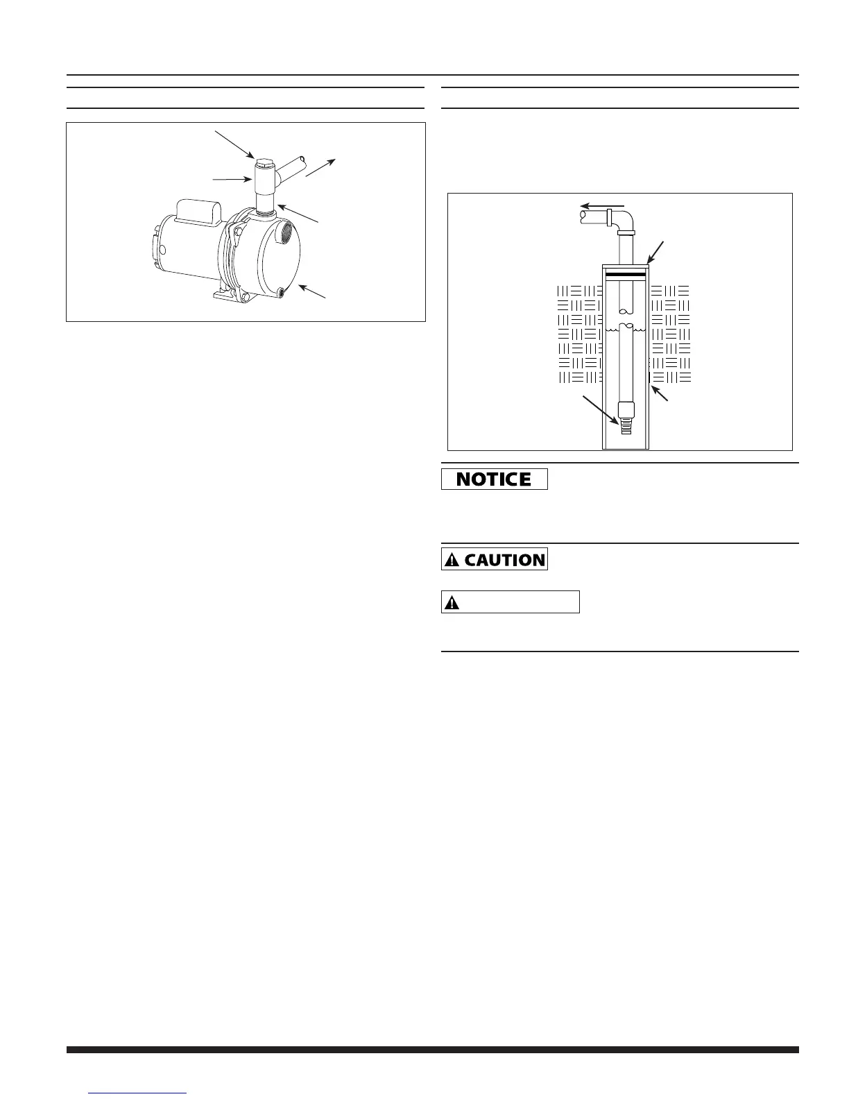
CONNECTION TO WATER SOURCE
PIPE PLUG
TO SPRAY
NOZZLES
SHORT
SECTION
OF PIPE
1-1/2” PIPE
TEE
PUMP
Figure 1
The maximum vertical suction lift of the pump from the water level is 25
feet.
DRILLED WELL INSTALLATION
1. Install a foot valve on the first section of pipe (see Figure 2).
2. Lower the pipe into the well.
3. Add pipe until the foot valve is 10 feet below the lowest anticipated
water level.
TO PUMP
WELL
WELL
CASING
FOOT
VALVE
Figure 2
Leaking joints or couplings will allow air to
leak into the pipe and cause poor pump operation or difficulty priming
Make sure to use pipe joint compound or plumber’s seal tape on all
threaded pipe connections.
Locate foot valve no closer than 2 feet from the
bottom of the well so sand or sediment is not drawn into the system.
MISE EN GARDE
Placer le clapet de pied à moins de 60 cm
du fond du puits pour éviter que du sable ou des sédiments ne soient
aspirés dans le système.
4. After the proper depth is reached, install a well seal or pitless
adapter to support the pipe.
5. Slope the horizontal pipe upward toward the pump to eliminate
trapping air.
6. When using a foot valve, a priming tee and plug above the well seal
is recommended.