EasyManua.ls Logo

Wayne WLS150 User Manual

Wayne WLS150
12 pages
To Next Page IconTo Next Page
Page #1 background imageLoading...
Page #1 background image
SPECIFICATIONS
POWER SUPPLY REQUIREMENT 120 V or 230 V, 60 Hz (WLS150)
230 V, 60 Hz (WLS200)
MOTOR Single Phase, Continuous Duty
HORSEPOWER 1 1/2 HP............... (WLS150)
2 HP ................... (WLS200)
CIRCUIT REQUIREMENT 15 A (minimum)
LIQUID TEMPERATURE RANGE 40° F- 120° F
650002-001 B 08/18© 2018, WAYNE/Scott Fetzer Company
CONSTRUCTION
MOTOR HOUSING Coated Steel
MOTOR SHAFT Stainless Steel
IMPELLER Thermoplastic
VOLUTE Cast Iron
PUMP SUCTION 2 in. NPT
PUMP DISCHARGE 1-1/2 in. NPT
Lawn Sprinkler Pump
www.waynepumps.com
PERFORMANCE
Model PSI Discharge Head
5 ft 10 ft 15 ft 20 ft 25 ft
WLS150
15 Gal / hr 4350 4200 3950 3700 3500
20 Gal / hr 3950 3700 3450 3250 3050
25 Gal / hr 3400 3200 3000 2800 2500
30 Gal / hr 2950 2750 2500 2150 1700
WLS200
15 Gal / hr - - 5300 5150
4850
20 Gal / hr 5300 5100 4850 4550
4300
25 Gal / hr 4800 4500 4250 4000
3750
30 Gal / hr 4200 3950 3750 3450
3100
Intended for Indoor Use Only
Operating Instructions and Parts Manual WLS Series
Please read and save these instructions. Read carefully before attempting to assemble, install,
operate or maintain the product described. Protect yourself and others by observing all safety
information. Failure to comply with instructions could result in personal injury and/or property
damage! Retain instructions for future reference.

Other manuals for Wayne WLS150

Question and Answer IconNeed help?

Do you have a question about the Wayne WLS150 and is the answer not in the manual?

Wayne WLS150 Specifications

General IconGeneral
BrandWayne
ModelWLS150
CategoryWater Pump
LanguageEnglish

Summary

Pump Specifications and Construction

Power Supply and Motor Details

Information on power requirements, motor type, horsepower, and circuit needs.

Pump Construction Materials

Details on materials used for pump housing, shaft, impeller, and volute.

Pump Inlet and Discharge Ports

Specifies the NPT sizes for the suction and discharge connections.

Liquid Temperature Range

Defines the operational temperature limits for the fluid handled by the pump.

Pump Performance Data

Flow Rate vs. Discharge Head

Table showing pump performance (Gal/hr) at various discharge heads for different models.

Product Description and Safety Information

Product Description and Unpacking

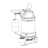
Overview of the pump's purpose and instructions for inspecting the unit upon receipt.

Safety Signal Words and Hazard Classifications

Explanation of signal words (Danger, Warning, Caution, Notice) and hazard symbols.

General Safety Precautions

Essential safety guidelines for using the pump, including electrical and water handling.

California Proposition 65 Warning

Disclosure regarding chemicals known to cause cancer or reproductive harm in California.

Water Source Information

Water Sources Diagram and Descriptions

Visual and textual explanation of various water sources: springs, lakes, wells, cisterns.

Installation and Piping Guidelines

General Installation Requirements

Guidelines for electrical connections, grounding, and protecting the pump from elements.

Pump Piping Installation Overview

Recommendations for using new pipe, supporting piping, and minimizing friction loss.

Suction Piping Requirements

Instructions for installing foot valves, pipe size, slope, and avoiding air leaks.

Discharge Piping Setup

Guidance on installing a priming tee for easy priming and connecting to spray nozzles.

Friction Loss Chart

Data on friction loss in PSI per 100 ft of pipe for various pipe sizes and flow rates.

Specific Installation Procedures

Connection to Water Source Diagram

Illustrates pump connection with a discharge tee for spray nozzles.

Drilled Well Installation Steps

Instructions for foot valve placement, pipe lowering, and sealing the wellhead.

Foot Valve Placement Caution

Warning about locating the foot valve to prevent sediment intake.

Additional Installation Methods

Driven Well Installation

Steps for installing a packer-type foot valve or in-line check valve in a driven well.

Dug Well, Cistern, Lake, Spring Installation

Guidance for installing foot valves and protecting pipes in various water sources.

Pipe Protection Warning

Caution to protect inlet pipes from swimmers, wildlife, and debris.

Electrical Connections and Wiring

Electrical Connection Requirements

Instructions for connecting to a dedicated circuit breaker and grounding the motor.

Voltage Selector and Wiring Diagrams

Guide to selecting voltage and connecting wires, including diagrams.

Recommended Fusing and Wiring Data

Chart providing fuse, voltage, wire size, and distance recommendations for motors.

Operation, Priming, and Maintenance

Pump Operation Precautions

Warnings against running the pump dry or with a closed discharge.

Pump Priming Procedure

Step-by-step guide to filling and starting the pump for initial operation.

Maintenance and Winter Draining

Guidance on motor ventilation, lubrication, and draining the system for winter.

Troubleshooting Common Issues

Motor Will Not Run

Troubleshooting steps for a pump motor that fails to start.

Motor Overheating or Tripping

Diagnosing causes for motor running hot and overload kick-off.

No Water Delivery or Low Capacity

Resolving issues with no water delivery, low capacity, or air suction.

Replacement Parts and Support

Replacement Parts List

List of available replacement kits for WLS series pumps with part numbers.

Customer Support Information

Contact details and required information for ordering parts or seeking support.

Limited Warranty Information

Warranty Coverage Details

Explains the one-year limited warranty for WLS Series pumps.

Warranty Exclusions and Limitations

Details what the warranty does not cover and legal disclaimers.

Warranty Claim Procedure

Instructions on how to make a warranty claim and what documentation is needed.

Related product manuals