8 Servicing Work DBW 2010 / 2016
805
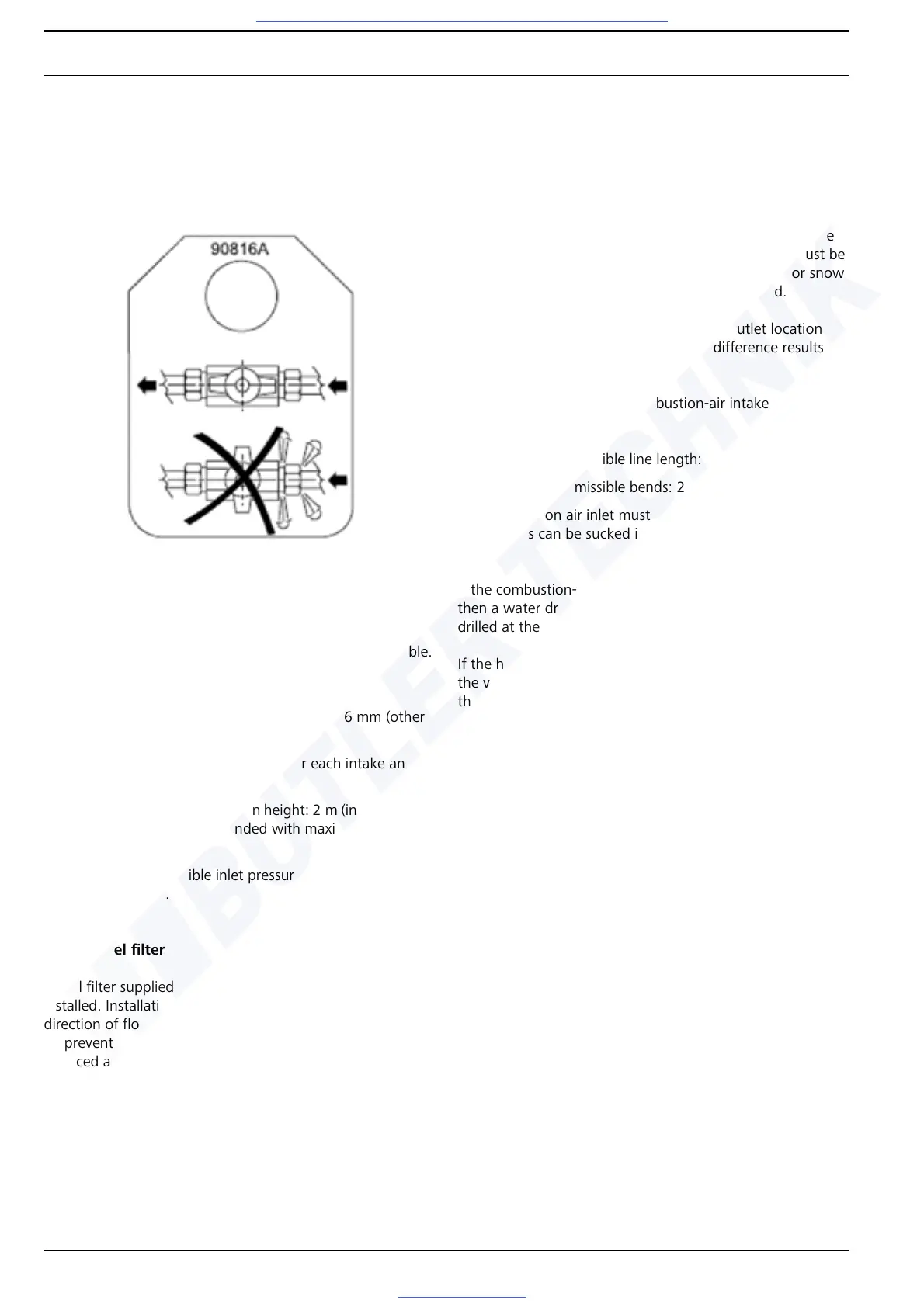
When installing a shut-off device in the return line, a notifica-
tion sign must be mounted in a highly visible location.
IMPORTANT
Operation with a closed return line will result in damage to
the fuel pump. Fuel can escape. Danger of fire!
Unsupported fuel lines must be secured to prevent them sag-
ging.
The installation of an additional fuel pump is not permissible.
Permissible dimensions of fuel lines:
• Inside diameter for intake and return line: 6 mm (other
diameters on request).
• Maximum permissible line length for each intake and re-
turn line: 10 m
• Maximum permissible suction height: 2 m (installation of
a check valve is recommended with maximum suction
height)
• Maximum permissible inlet pressure: 0.3 bar for intake
and return line.
8.6.2.2 Fuel filter
A fuel filter supplied or approved by Webasto must be
installed. Installation should be vertical if possible, while the
direction of flow is horizontal.
To prevent malfunctions, the filter or filter insert must be
replaced at least once a year, and with heavily soiled fuel
more often, to prevent malfunctions.
8.6.3 Combustion air supply
IMPORTANT
The statutory regulations for the installation must be
observed (see 1.6).
Under no circumstances may the combustion air be taken
from areas occupied by people. The combustion air intake
opening must not point in the direction of travel. It must be
located so that it cannot become clogged with dirt or snow
and intaking of splash water is not to be expected.
The combustion air inlet and exhaust-gas outlet location
must be chosen so that no air pressure difference results in
any vehicle operating mode.
Permissible dimensions of combustion-air intake line:
• Inside diameter: 55 mm
• Maximum permissible line length: 5 m
• Maximum permissible bends: 270 °C
The combustion air inlet must be positioned so that no
exhaust gas can be sucked in.
NOTE
If the combustion-air intake pipe cannot be installed uphill,
then a water drain hole with a diameter of 4 mm must be
drilled at the lowest point.
If the heater is installed in a common installation space near
the vehicle tank, the combustion air must be taken in from
the outside and the exhaust gas discharged into the atmos-
phere. The openings must be splash-proof.
If the heater is installed in a closed installation box, a ventila-
tion opening is required:
DBW 2010 / 2016 20 cm
2
If the temperature in the installation box exceeds the permis-
sible ambient temperature of the heater (see Section 4,
"Technical Data"), then the ventilation opening must be
enlarged after consulting Webasto.
8.6.4 Exhaust pipe
IMPORTANT
The statutory regulations for the installation must be
observed (see 1.6).
The opening of the exhaust pipe must not point in the direc-
tion of travel.
The exhaust pipe opening for combustion air must be located
so that it cannot become clogged with snow and mud.
Fig. 803 Notification sign
 Loading...


