Do you have a question about the Webasto Thermo Top Z/C - D and is the answer not in the manual?
Explains identification marks and italicized sections for quick overview of working steps.
Details type approvals according to ECE-R 10/122 and binding EU directives for installation.
Specifies use of operating and vehicle-specific installation instructions.
Explains applications like parking heater and auxiliary heater for passenger compartments.
Details parking heater use in Class M1 vehicles for compartment heating and defrosting.
Describes auxiliary heater function, operating independently of the vehicle engine.
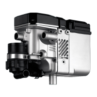
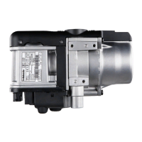
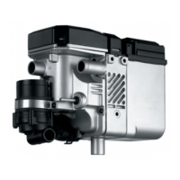
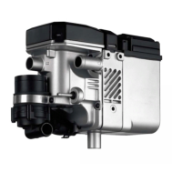
Lists different heater models and their fuel types.
Covers body protection, fire risk prevention, ventilation, and preferred engine compartment placement.
Details restrictions like coolant connections not facing down and avoiding exhaust radiation areas.
Instructions for positioning the label for easy reading and retaining current year information.
Details mounting the heater bracket with M6 bolts and specified torque.
Provides a visual guide with component legends for a typical vehicle installation.
Describes connecting the heater to the vehicle cooling system and preferred integration points.
Covers hose clamping, tightening torque, system bleeding, and using approved hoses.
Explains integrating the circulation pump on the pressure side of the heater inlet.
Details checking the entire coolant system for leaks after installation.
Discusses fuel integration methods and precautions when drawing from engine lines.
Explains installing a fuel standpipe in the fuel removal unit for tank connection.
Details line lengths, routing in cool areas, avoiding heat, and securing fuel lines properly.
Specifies using only Webasto-approved fuel lines for installation.
Shows hose connection method with clamps and torque, emphasizing leak prevention.
Introduces the metering pump and its specific installation criteria.
Advises against installing the metering pump near hot parts and suggests placement near the tank.
Covers vibration-damping mounting and position restrictions for pump self-ventilation.
Instructions for affixing a "Switch off heater when refuelling" sticker at the fueling point.
Notes on operating with low-temperature fuels and the effect of additives.
Covers intake opening placement, avoiding clogging, and routing in cool, protected areas.
Specifies installation position for the air intake silencer between 0° and 90° downwards.
Details mounting the combustion-air intake pipe and securing the silencer.
Specifies dimensions, bending, and total length requirements for the exhaust pipe.
Mandates the use of an exhaust silencer and its minimum installation distance from the heater.
Covers fastening exhaust components, ensuring distances, draining condensate, and outlet positioning.
Refers to Fig. 18 for the electrical connection of the heater control unit.
Emphasizes visibility of the tell-tale indicator and warns against pressing the timer display during installation.
States that installation of other controls like Telestart follows specific instructions.
Explains vehicle fan control via relay, current consumption limits for Thermo Top Z.
Describes connecting the summer/winter switch and insulating wires for Thermo Top E/C.
Refers to Fig. 18 for system wiring diagrams and specifies line cross-section applicability.
Stresses safety precautions, reading operating instructions, and careful bleeding of coolant and fuel systems.
Advises proceeding according to the workshop manual to remedy faults and prevent lock-out.
Lists specifications for the circulation pump, including volume flow rate, voltage, and dimensions.
Provides technical specifications for DP2 (Petrol) and DP30.2 (Diesel) metering pumps.
Details EC approval marks, fuel types, heat flow, fuel consumption, and power consumption for various models.
| Fuel Type | Diesel |
|---|---|
| Heating Power | 5 kW |
| Rated Voltage | 12V / 24V |
| Voltage | 12V |
| Operating Temperature Range | -40 °C to +70 °C |






 Loading...