Marine heating system Installation Instructions
© Webasto Global Comfort Solutions
®
9
5 Exhaust
5.1 Exhaust system
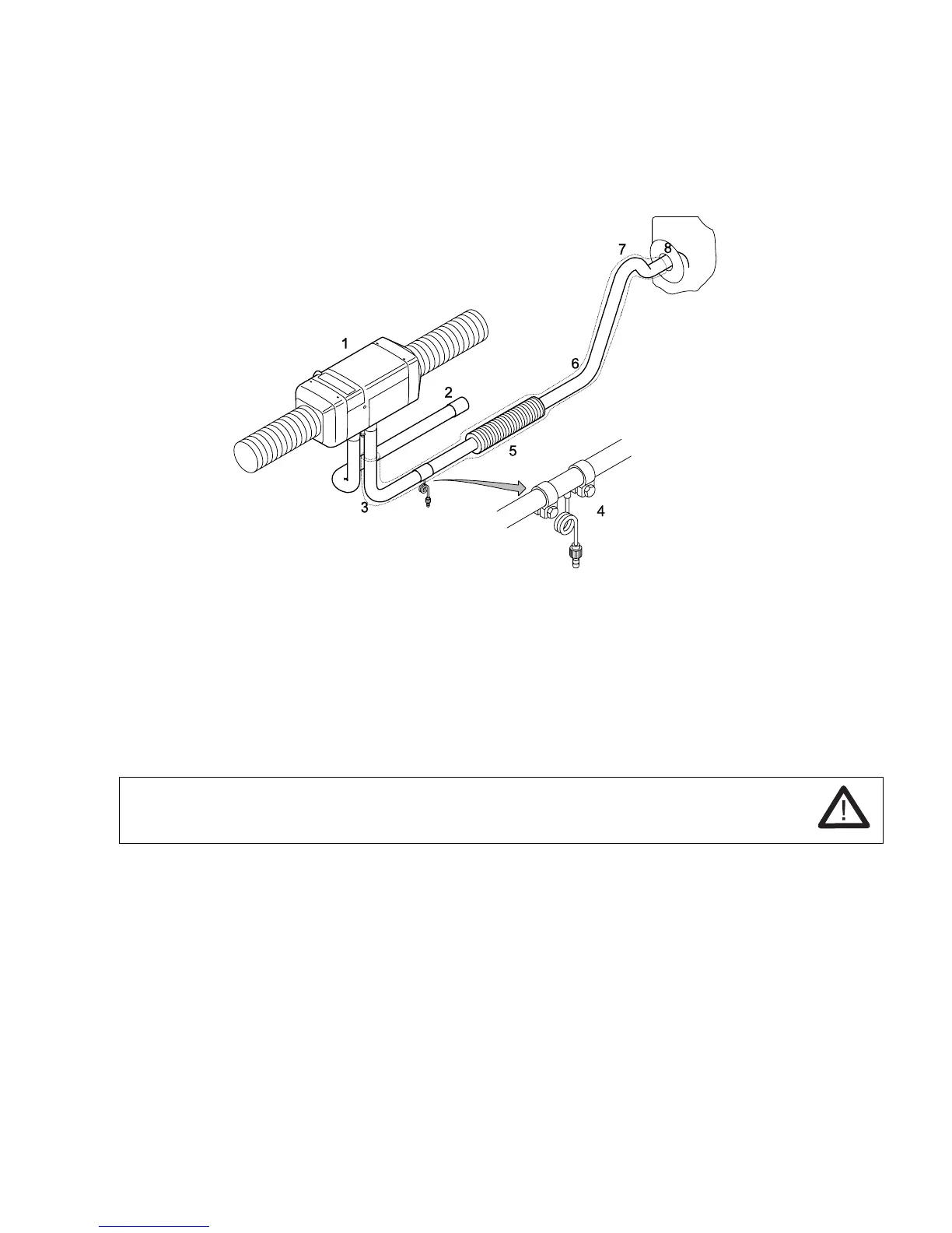
Feed the combustion gasses out of the boat through the exhaust system.
1) Heater; 2) Combustion air intake; 3) Flexible stainless steel exhaust pipe; 4) Condensation drain;
5) Exhaust gas sound absorber; 6) Isolation; 7) Goose neck; 8) On-board duct
5.2 Exhaust outlet
Outlet arrangement:
• Position the exhaust outlet where as little water spray can enter as possible.
Recommendation:
Sail boat: in the stern transom.
Motor boat: in the lateral side wall.
WARNING! Do not position the exhaust outlet underneath or next to ventilation
equipment, window openings or the heating air intake (risk of suffocation).
• at least 60 cm above the water line so that no water can enter when the boat heels.
• do not connect to the engine or generator exhaust line (higher pressure, damage to the
heater).
• not in the direction of movement of the boat (higher wind pressure).
• not where it can be covered easily, e.g. by the fender.
Wall ducts:
• Choose the design and installation position: minimize rain water ingress.
• Only metals ducts are permissible. Use insulating washers for thermal isolation from the walls.
Use properly fitting seals (minimizing water ingress).
If additional seals are needed: use heat-resistant sealant only.
• Wall ducts: Not sealable; not with self-opening valves.
 Loading...