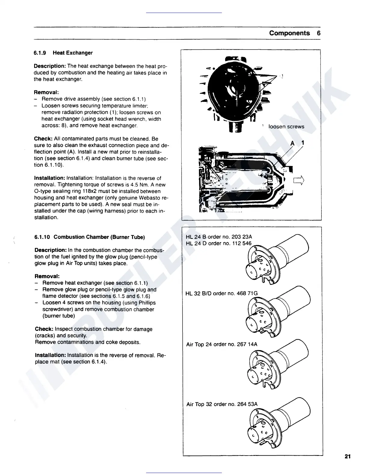
6.1.9 Heat Exchanger
Description:
The heat exchange between
the
heat pro-
duced by combustion and the heating air takes place
in
the heat exchanger.
Removal:
- Remove drive assembly (see section 6.1.1)
- Loosen screws securing temperature limiter;
remove radiation protection ( 1
);
loosen screws on
heat exchanger (using socket head wrench, width
across: 8), and remove heat exchanger.
Check: All contaminated parts must
be
cleaned. Be
sure to also clean the exhaust connection piece and de-
flection point
(A). Install a new mat prior to reinstalla-
tion (see section 6.1.4) and clean burner tube (see sec-
tion 6.1.10).
Installation: Installation: Installation
is
the reverse of
removal. Tightening torque of screws
is
4.5
Nm.
A new
O-type sealing ring
118x2
must
be
installed between
housing and heat exchanger (only genuine Webasto re-
placement parts to
be
used). A new seal must
be
in-
stalled under the cap (wiring harness) prior
to
each in-
stallation.
6.1.10 Combustion Chamber (Burner
Tube)
Description:
In
the
combustion chamber
the
combus-
tion of the fuel ignited by the glow plug (pencil-type
glow plug
in
Air
Top
units) takes place.
Removal:
- Remove heat exchanger (see section 6.1.1)
- Remove glow plug or pencil-type glow plug and
flame detector (see sections 6.1.5 and 6.1.6)
- Loosen 4 screws
on
the housing (using Phillips
screwdriver) and remove combustion chamber
(burner tube)
Check: Inspect combustion chamber tor damage
(cracks) and security.
Remove contaminations and coke deposits.
Installation: Installation is the reverse of removal. Re-
place mat (see section 6.1.4).
-
HL
24
8 order no. 203 23A
HL
24
D order no.
112
546
Air Top 24 order no. 267 14A
'\)
Air Top 32 order no. 264 53A
'\)
Components 6
' loosen screws
A 1
21
 Loading...