20
6 Components
6.1.8 Temperature Limiter
and
Safety Switch
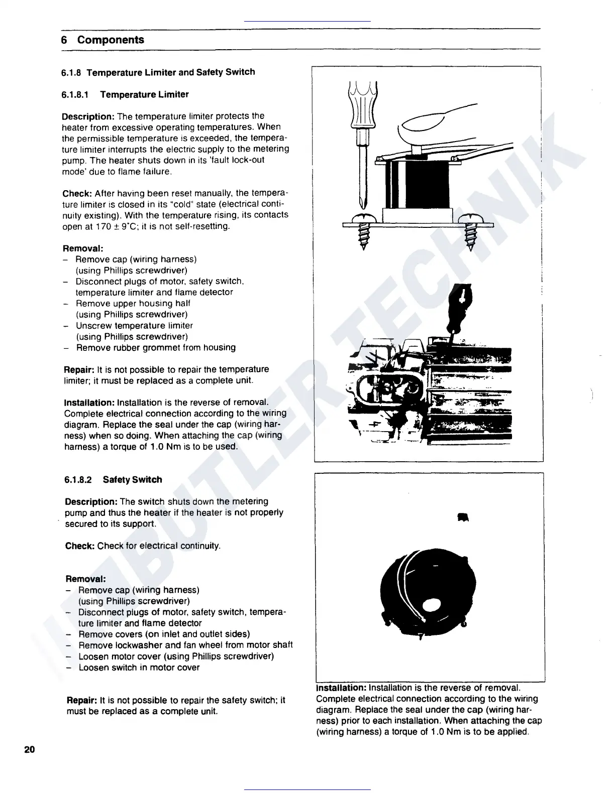
6.1.8.1 Temperature Limiter
Description: The temperature limiter protects the
heater from excessive operating temperatures. When
the
permissible temperature
is
exceeded, the tempera-
ture limiter interrupts the electric supply to the metering
pump. The heater shuts down
in
its
'fault lock-out
mode' due
to
flame failure.
Check: After having been reset manually, the tempera-
ture limiter
is
closed in its "cold" state (electrical conti-
nuity existing). With the temperature rising, its contacts
open
at
170 ±
g·c;
it is not self-resetting.
Removal:
- Remove cap (wiring harness)
(using Phillips screwdriver)
Disconnect plugs of motor. safety switch,
temperature limiter and flame detector
Remove upper housing half
(using Phillips screwdriver)
Unscrew temperature limiter
(using Phillips screwdriver)
Remove rubber grommet from housing
Repair: It
is
not possible to repair the temperature
limiter; it must
be
replaced as a complete unit.
Installation: Installation is the reverse
of
removal.
Complete electrical connection according to the wiring
diagram. Replace the seal under the cap (wiring har-
ness) when
so
doing. When attaching the cap (wiring
harness) a torque
of
1.0 Nm is
to
be
used.
6.1.8.2 Safety Switch
Description: The switch shuts down the metering
pump and thus the heater if the heater
is
not properly
secured to its support.
Check: Check for electrical continuity.
Removal:
- Remove cap (wiring harness)
(using Phillips screwdriver)
- Disconnect plugs
of
motor, safety switch, tempera-
ture limiter
and
flame detector
- Remove covers (on inlet
and
outlet
sides)
- Remove lockwasher and
fan
wheel from motor shaft
- Loosen motor cover (using Phillips screwdriver)
- Loosen switch in motor cover
Repair: It
is
not possible to repair the safety switch; it
must
be
replaced as a complete unit.
•
Installation: Installation is the reverse of removal.
Complete electrical connection according to the wiring
diagram. Replace
the
seal under the
cap
(wiring
har-
ness) prior to each installation. When attaching the cap
(wiring harness) a torque
of
1.0 Nm is to be applied.
 Loading...