3 Functional Description
HL 90
302
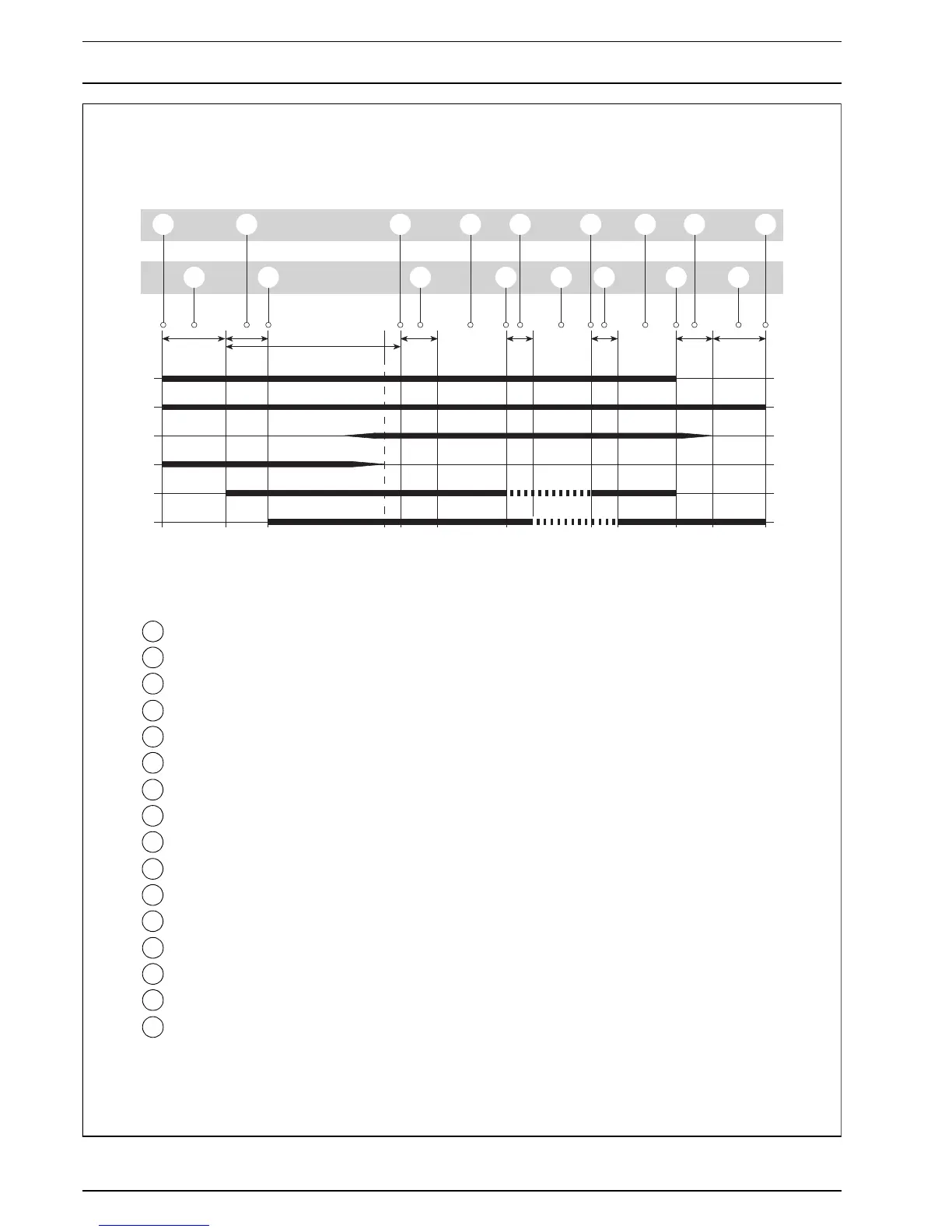
Fig. 301 Functional Diagram
A
B
C
D
E
F
✽
1
2
3
4 6
7
8
9
10
11
12
14
15
16
13
7
5
1 Switch on
2 Preheating 35 s
3 Fuel priming
4 Full load initiation
5 Safety period max. 100 s
6 Minimum full load time 60 s
7 Combustion operation – full load
8 Room temperature (at rated value)
9 Transition from full load to part load 8 s
10 Combustion operation – part load
11 Room temperature (below rated value)
12 Transition from part load to full load 10 s
13 Switch off
14 Optical run-down max. 40 s
15 Electronic run-down 150 s
16 Off
A Operating indicator light on
B Switch or room thermostat
(full load / part load) or timer
C Flame sensor
D Glow plug
E Dosing pump (full load / part load)
F Combustion air fan (full load / part load)
* In case of no flame condition
automatic repeat start
(25 s preheating, 80 s safety period)
 Loading...