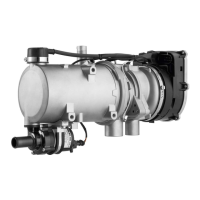
HL 90
7 Circuit Diagrams and Examples for Electrical Installation
701
7 Circuit Diagrams and Examples
for Electrical Installation
7.1 General
Circuit diagrams (Fig. 701 to 703) show possible heater
circuits for HL90 with
• timer and room thermostat
• switch (full load - part load) and ventilation
• room thermostat (full load - part load) and ventilation
Examples (Fig. 704 and 705) show the proper electrical
installation for operation with switch and ventilation
(Fig. 704) as well as the use of the standard wiring
harness (Fig. 705).
 Loading...