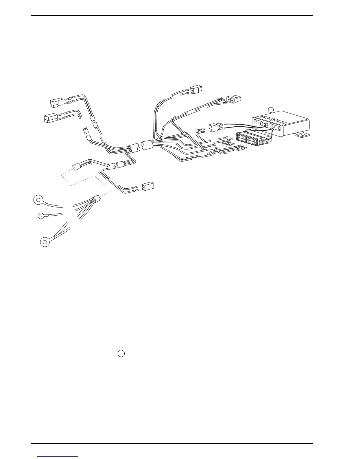
7 Circuit Diagrams and Examples for Electrical Installation
HL 90
706
X2 Intermediary connector dosing pump
X3 Connector flame sensor
X4 Connector glow plug resistor
X5 Connector temperature limiter
X7 Connector relay/fuse
X0;
X00 Connector glow plug
1 Control unit
Fig. 705 Example for Electrical Installation "Standard Wiring Harness"
rt=2
br=X00
br=14
gn=6
rt/bl=C5
X4
br=12
bl=10
rt/bl=05
br=2
ge=2
ge=1
br=C12
bl=C10
gn=C6
sw=C1
sw=1
1
2
3
4
5
6
7
8
9
10
11
12
13
14
B
C
X2
X5
2
1
2
1
X3
1
A
B
C
2
1
X7
br=X7-2
ge=X4-1
br=X3-1
br=XC-12
X00
X0
X00
rt=3
br=2
vi=4
ge=1
vi=4
 Loading...