9 Repair
HL 90
902
9.2 Disassembly and Assembly
9.2.1 Control Unit, Replacement
9.2.1.1 Removal
1. Disconnect electrical connector on control unit.
2. Remove screws (14, Fig. 901) and control unit (13).
3. Perform procedures on components after
disassembly (refer to 9.1.1).
9.2.1.2 Installation
1. Locate control unit (13, Fig. 901) in installation
position and secure with screws (14).
2. Torque screws with 2.5 ± 0.2 Nm.
3. Connect electrical connector to control unit.
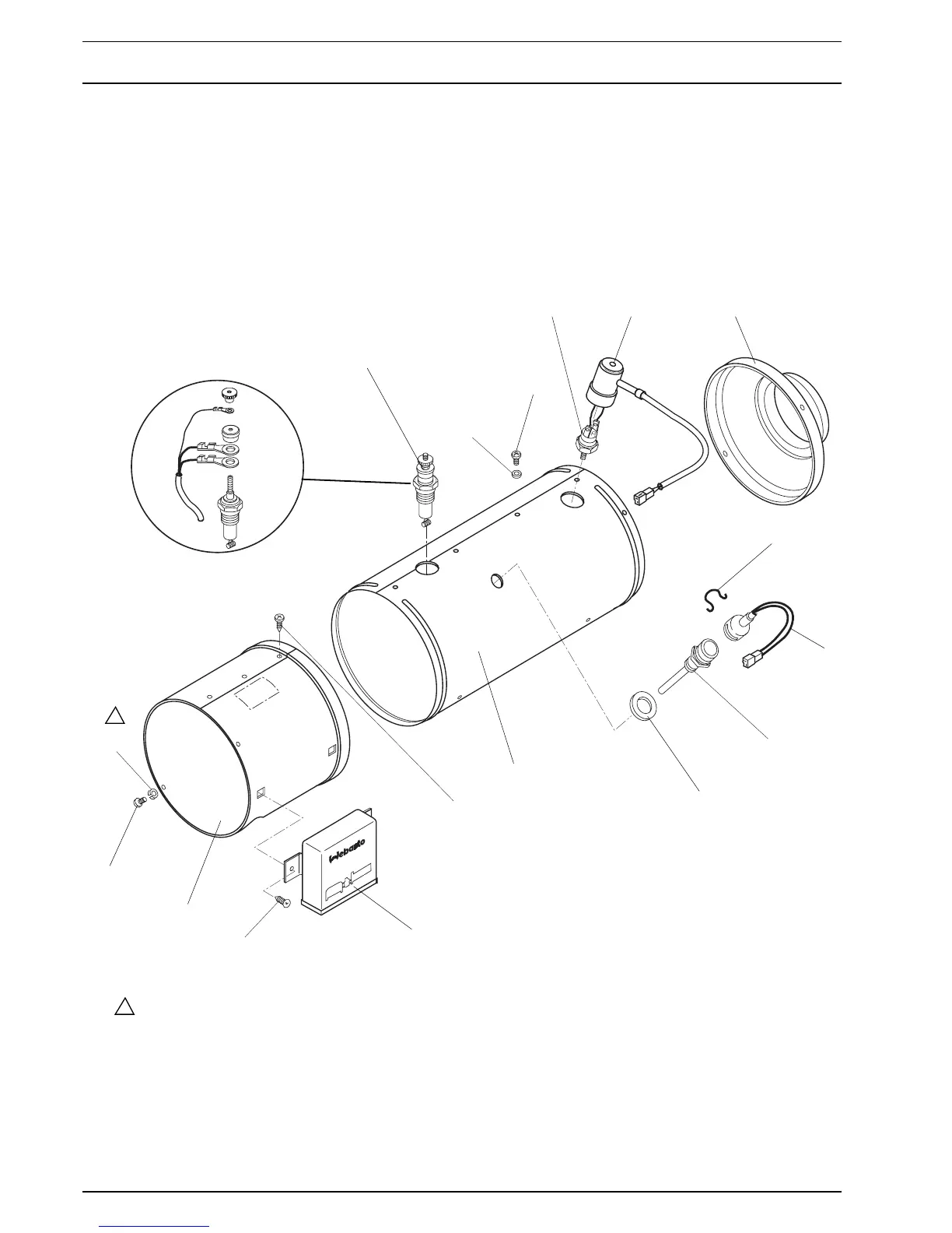
Fig. 901 Replacement of Control Unit, Glow Plug, Flame Sensor and Temperature Limiter
ge
br
br
A
B
C
1 Glow plug
2 Lock washer
3Screw
4 Temperature limiter
5 Silicone cap
6 End cap
7 Retaining clip
8 Flame sensor
9 Flame sensor receptacle
10 Grommet
11 Outer case
12 Screw (3)
13 Control unit
14 Screw (2)
15 Half case
16 Screw (3)
17 Spring washer (3)
Spring washers (17) not
applicable for orifice plate
made of plastic.
17
16
15
14
13
12
11
10
9
8
7
1
2
3
4
5
6
Detail A
1
1