Installation
www.webasto.us Webasto Product N.A., Inc. www.techwebasto.com
13
Since the lines cannot be routed with a constant rising gradient, the internal diameter must not exce ed a certain size. Air or
gas bubbles will accumulate in lines with an internal diameter of more than 4 mm and will cause malfunctions if the lines
sag or are routed downwards. The lines should not be routed downwards from the metering pump to the heater.
Unsupported fuel lines must be secured to prevent them sagging. The y must be instal led in such a way th at they ca nnot b e
damaged by flying debre and high temperatures (e.g. exhaust line).
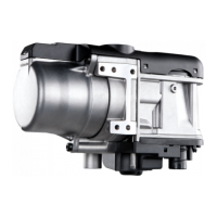
Connecting two pipes with a hose
The correct procedure for connecting fuel lines with hosing is
illustrated in Fig. 8
Ensure that there are no leaks.
Installation location
Before installing the metering pump, ensure that the maximum
pressure occurring at the pickup point is less than 3 PSI. It is
advisable to install the metering pump in a cool place. The
maximum ambient temperature must not exceed 104°F (40 °C) at
any time during operation.
The metering pump and fuel lines must not be installed within
range of the radiated heat from hot vessel parts. A heat shield must
be used if necessary.
The pump should ideally be installed near the vessels fuel tank.
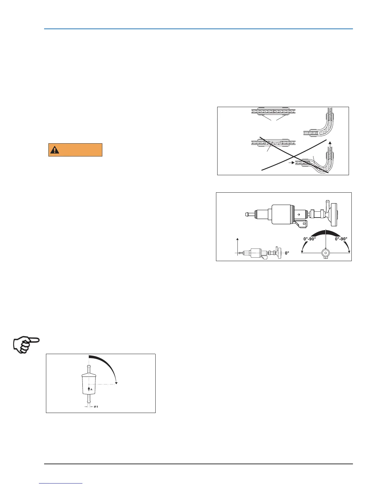
Installation and attachment
The metering pump must be secured with the supplied vibration-damping mounting clamp. Its installation position is
limited as shown in Fig. 9 in order to ensure effective auto-bleeding.
Fuel filter
Only a Webasto filter P/N: 50487171A is permitted when a fuel filter is needed. Install vertically if possible. (See Fig.10).
NOTE: Ensure to follow the correct fuel filter direction flow marked on the side of the filter.
Clip
Bubble
Correct
Wrong
Bubble
Fig. 8 Pipe / Hose Connections
WARNING
12 V and 24 V – diesel only
Fig. 9 Metering Pump
0° - 90°
Fig. 10 Fuel Filter
 Loading...