Marine heating system Installation Instructions
12 © Webasto Global Comfort Solutions
®
6 Combustion air supply
6.1 Combustion air circulation
Observe carefully:
• Intake from are well ventilated from the outside at ambient pressure and/or directly from the
outside.
Do not extract intake air from accommodation/cabins. Danger of suffocation!
• Intake location: no intake of exhaust gasses (from heater and/or engine).
6.1.1 Intake of combustion air from area well ventilated from the outside
(locker, storage area or engine compartment)
• No on-board ducts needed.
• Intake area must be at ambient pressure and be sufficiently ventilated to the outside.
• When intake is in the engine compartment: the engine compartment ventilation blower may
not create an under-pressure or overpressure in the engine compartment.
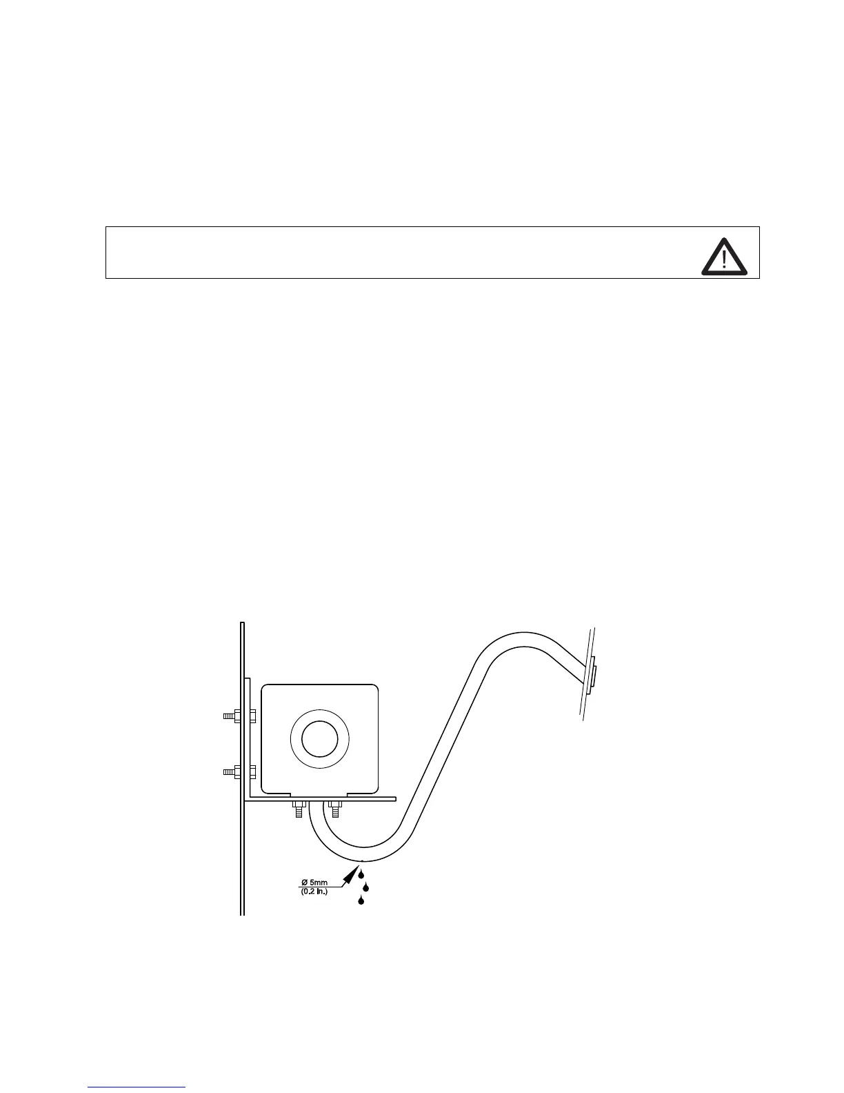
6.1.2 Combustion air intake directly from outside
• Use separate on-board ducts when an intake from a ventilated area is not possible.
• Route the end of the intake hose like a goose neck, as shown in the illustration.
• Do not arrange on-board ducts in the direction of travel (other pressure build-up and water
ingress in the intake pipe is possible).
• Make a drain hole at the lowest point, as shown in the illustration.
• Route the hose so that it is kink free.
Combustion air intake from outside through an on-board duct
 Loading...