Marine heating system Installation Instructions
24 © Webasto Global Comfort Solutions
®
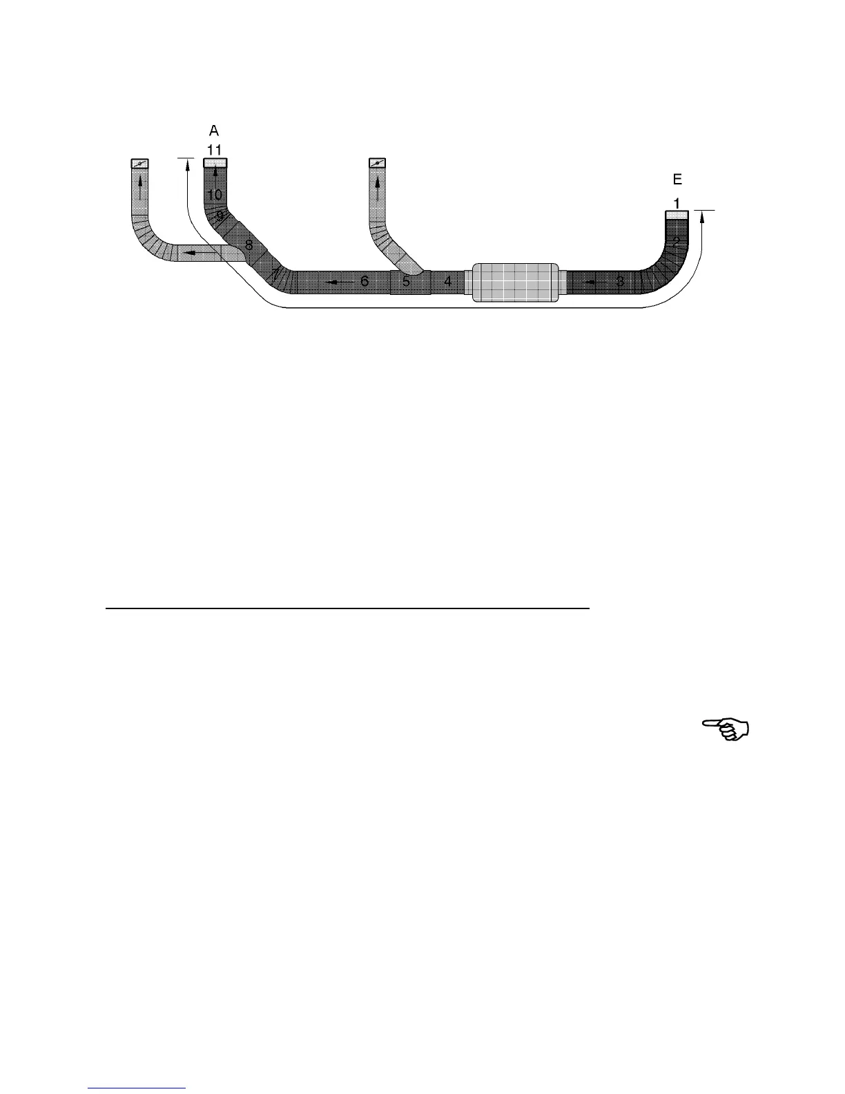
Determine the resistance points of the planned air lines: total the separate resistance points in the
main line and add the components used.
Main line begins at intake point E and ends at open outlet A.
Example: Air Top 5000
®
Air line
No. Components Resistance points
1 Intake grille, Ø 90 mm 65
2 1 m hot air hose, Ø 90 mm curved 25 + 6
3 0.5 m hot air hose, Ø 90 mm straight 0.5 x 25
4 0.4 m hot air hose, Ø 90 mm straight 0.4 x 25
5 Branch, 90/60/90 16
6 1 m hot air hose, Ø 90 mm straight 25
7 0.5 m hot air hose, Ø 90 mm curved 0.5 x 25 + 6
8 Branch, 90/60/90 16
9 0.4 m hot air hose, Ø 90 mm curved 0.4 x 25 + 6
10 1 m hot air hose, Ø 90 mm straight 25
11 Outlet, Ø 90 mm with 90° shutters 33 _
Total 268 points
Total of 268 points is less than the upper limit of 375 points for Air Top 5000
®
: Interpretation is good
for flows.
Optimal air distribution:
• short hoses
• few curves
• no reduction of the total diameter
• non-shuttered outlet in main line.
• optimal flow branches and distributors.
 Loading...