Marine heating system Installation Instructions
© Webasto Global Comfort Solutions
®
29
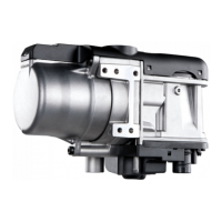
Places for removing the controller cover
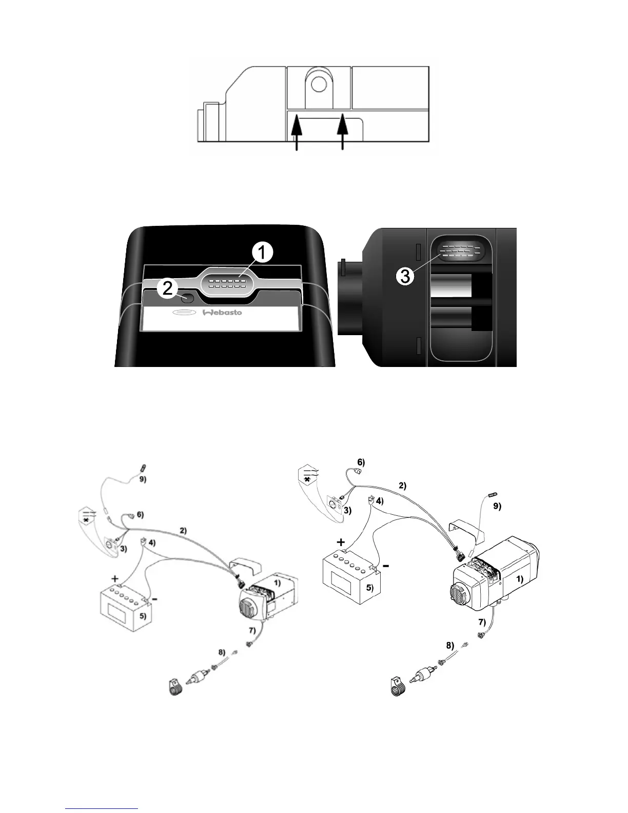
Connector locations for single cable harness to heater according to illustration. Plugs are coded
over sockets.
Connections: 1) AT 3500/5000ST
®
cable harness; 2) External temperature sensor; 3) AT 2000ST
®
cable
harness
Principles of connection of the main components for the Air Top 2000ST
®
and Air Top 3500/5000
®
as shown in the illustration. Details of wiring: see device-specific installation instructions.
1) Air Top 2000 ST
®
(left) / Air Top 3500/5000
®
(right); 2) Main cable harness; 3) Control or combi-timer;
4) Fuse 12V – 20A / 24V – 15A; 5) Battery; 6) Diagnostic connector; 7) Metering pump cable harness;
8) Extension cable for metering pump; 9) External temperature sensor
 Loading...