Thermo 90 5 Troubleshooting
503
Fig. 502 Failure Symptoms after Switch-off upon Failure (Sheet 2 of 2)
5.4 Visual Inspection for Assessment
of Burner Condition
Burner and evaporator have specific features indicating
their need for replacement or their serviceable condition.
The following describes the criteria
for a correct
inspection.
5.4.1 Burner Housing
• The starting air bore (Fig. 502) must not be clogged,
otherwise there will be no start.
Remedy
Carefully remove any contamination (e.g. with a wire
o
f 1.5 mm diameter). Remove glow plug first.
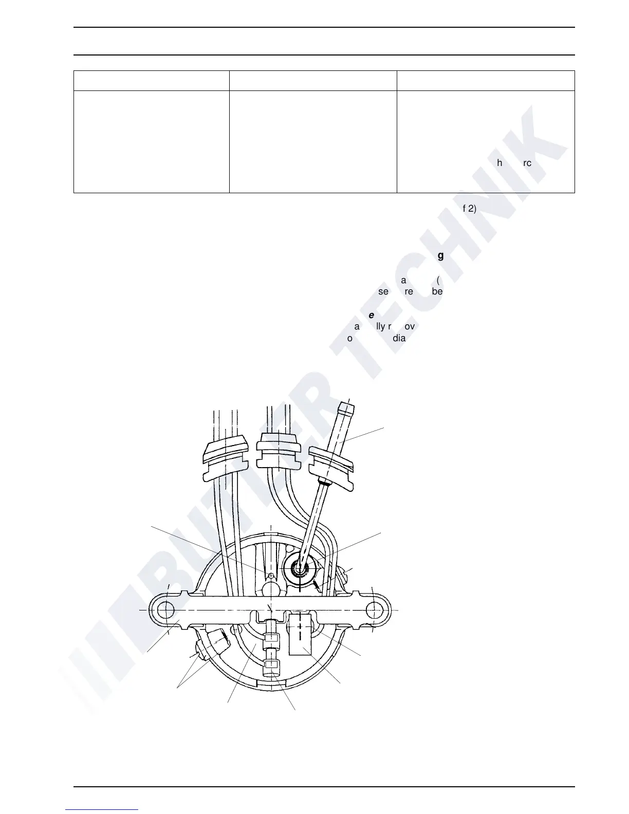
Fig. 503 Visual Inspection, Burner Real Wall
Failure Symptom Failure Symptom Remedy
8 Flash pulses
(combustion air fan defective)
Wiring Check wiring for damage,
open connections or short circuit
Combustion air fan defective Replace combustion air fan
9 Flash pulses
(glow plug defective)
Wiring Check wiring for damage,
open connections or short circuit
Glow plug defective Replace glow plug
1 Combustion Tube
2 O-Ring
3 Flame Sensor
4 Insulation
5 Glow Plug
6Housing
7Screw
8 Bracket
9 Starting Air Bore
1
2
3
4
5
6
7
8
9

 Loading...